3.6 Installing the circulation kit (optional)
The circulation kit is available for separate purchase.
Follow the steps below to install it.
1. Makesurethesystemisturnedoanddepressurized.
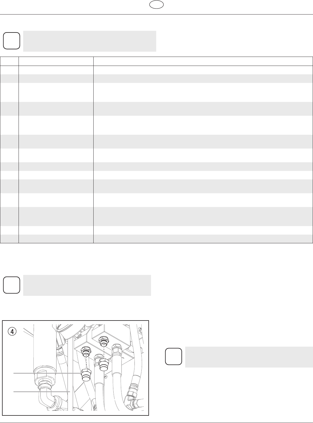
2. Remove the two inlet plugs (Fig. 4, item 1) from the bottom of
the hose heater manifold. Remove return tubes (2).
1
2
3. Thread a shut-o valve (Fig. 3, item L1) from the circulation kit
into each of the ports underneath the hose heater manifold.
Thread the longer return tubes (Fig. 2, item F) underneath
each of the PRIME/SPRAY valve manifolds.
4. Attach a hose to each of the shut-o valves. Run the hoses
(Fig. 3, item L2) and return hoses (Fig. 3, item F) back towards
the material containers and thread into their respective ports
on the desiccant dryers.
Refer to section 3.3 for Clearance Diagram.
Helix 9
GB
System Description
3.5 Component Description - with circulation
This conguration is only possible with the purchase of
circulation kit P/N 0138914, sold separately. The parts
included in the kit are labeled with an asterisk (*).
Item Description Function
A Component Pump A In a two-component system, Component Pump A typically pumps the ISO or activator material.
B Component Pump B In a two-component system, Component Pump B typically pumps the resin material.
C Heater Block Materialowsfromthesupplycontainersintotheuidpumps,wherethematerialispressurized
to the desired pressure(s), based on the Control Panel settings. The heater block heats the material
on its way to the material pumps.
D Control Panel The control panel contains all of the system controls that allow the sprayer to function properly, as
well as being the main display panel that gives information about the system.
E PRIME/SPRAY knob The PRIME/SPRAY knob directs material to the spray hose when in the SPRAY position and to the
prime hoses when in the PRIME position. Turning the PRIME/SPRAY knob will relieve any pressure
built up in the system.
F Prime hoses When the PRIME/SPRAY knobs are set to PRIME, spray material will circulate into the Component
pumps and then out of the prime hoses.
G Inlet valves The inlet valves allow material to be drawn from the material containers into the system. They can
be turned o in order to prevent material from entering the system.
H Supply hoses The two supply hoses deliver uid from the supply drums to the Component pumps.
I Dual heated hose The dual heated hose delivers spray material from the two Component Pumps to the spray gun.
J Transfer pump The two transfer pumps pump material from the supply containers, into the supply hoses and then
to the Component Pumps. The transfer pumps are powered by an air compressor.
Desiccant dryer The Desiccant dryers remove any moisture that is present in the air pockets left by the removal of
material from the supply drums.
L* Circulation valves / hoses When open, the circulation valves (L1) allow material to circulate through the heater block and
back through the hoses (L2) into the supply containers. This allows the material to be heated more
quickly.
M Transfer pump air hose The transfer pump air hose delivers air from the compressor to the transfer pumps.
N Agitator The agitator stirs the material on the resin (B) side material container.


