5. Setup
In order to prevent accidental startup, make sure the
system’s power cord is not connected during setup,
until instructed to do so.
5.1 Locate the System
1. Locate the system on a level surface. Refer to dimensions in
section 3.3 for clearance and mounting hole dimensions.
2. Mount in a dry area.
3. For best results, the machine should be bolted into place.
5.2 Install the Transfer Pumps
i
The transfer pumps draw material directly from the
spray material container to component pumps in the
system. The transfer pumps are powered by an air
compressor.
Refer to section 3.1 for the corresponding illustrations to the steps
below.
1. Install the transfer pumps into Component A and Component
B supply containers.
a. With certain exceptions, the “A” component (hardener) should
be located on the “A” side of the system.
b. With certain exceptions, the “B” component (resin) should be
located on the “B” side of the system.
Consult the spray material’s manufacturer if you are
unsure about which Component Pump is compatible
with each individual spray component.
2. Seal the container holding Component A material and install
the desiccant dryer in the vent hole.
3. If necessary, install an agitator into the Component B material
container.
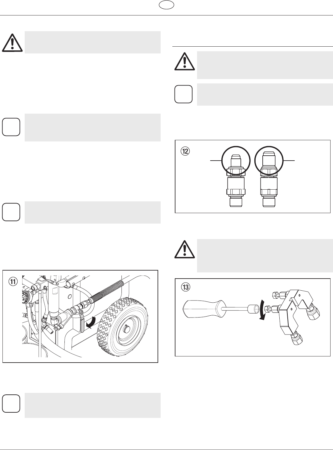
4. Make sure the Component A and Component B inlet valves
are in the closed position (handle should be 90º to the valve).
5. Attach the transfer pump air hose to their individual air
ttings.
6. Connect the other end of the transfer pump air hose to the
powered air pressure supply.
i
Do not install shuto valves downstream of the
prime tubes. The PRIME/SPRAY valves function as
overpressure relief valves when set to SPRAY.
5.3 Connect the Hoses
Connect the Heated Hoses
Attention
The heated hose assembly and dual whip hose
come pre-installed with the system and should
not be removed or disassembled unless it is being
completely replaced.
Refer to the Helix Heated Hose Manual P/N 0138875
included with your system.
1. AttachtheJICttings(packagedseparatelywiththeheated
hose set) to their appropriate whip hoses.
a. ConnectthesmallerJICttingtothe“A”sidewhiphose.
b. ConnectthelargerJICttingtothe“B”sidewhiphose.
2. Remove the coupling block from the spray gun (refer to the
spray gun manual).
3. Close gun manifold valves A and B.
Attention
Always close the manifold valves if the system is idle
for more than 1 minute under heat and/or pressure.
Failure to do so can cause a pressure imbalance
which can then lead to a material “crossover” inside
the gun, leaving the gun inoperable.
Helix 15
GB
Setup
