VCN Access Point Features 15
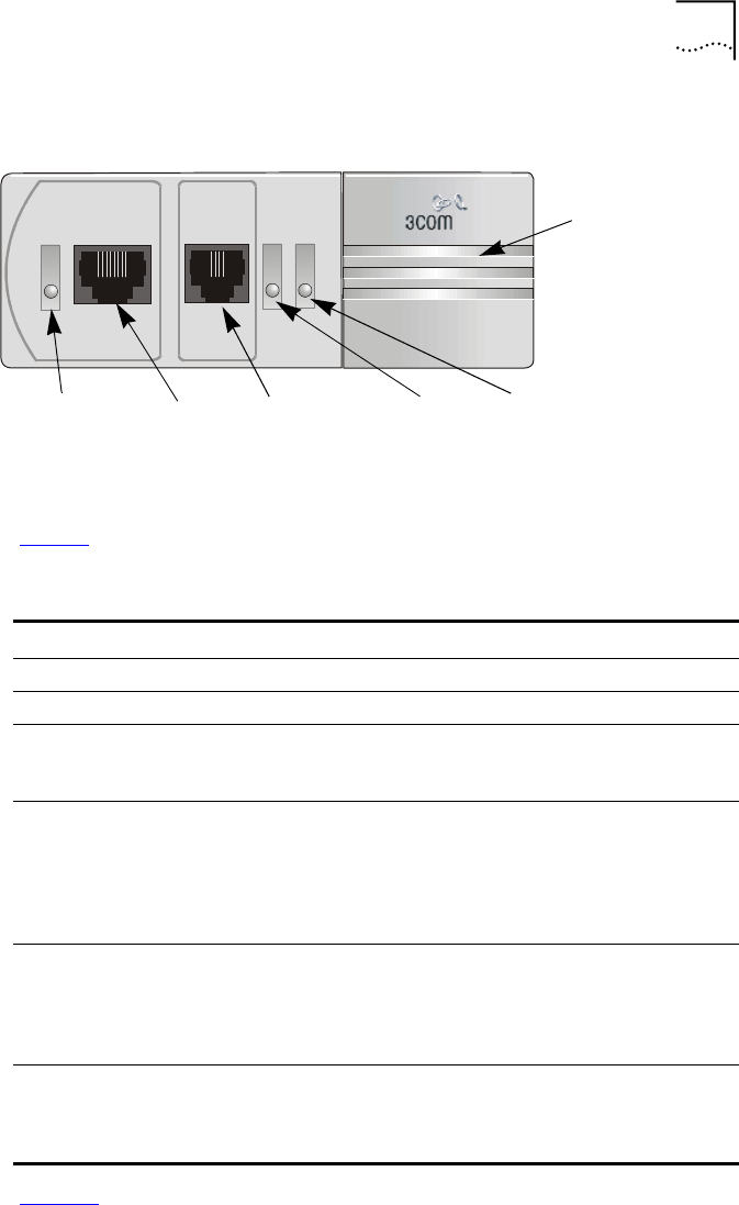
Figure 4
The VCN AP Unit Front View
Ta b le 3 describes the LEDs and connectors on the front panel.
Figure 5
displays the back panel of the VCN AP.
Fax-ModemETHERNET
Line
Power
Ethernet
LED
Ethernet
port
Fax-Modem
port
Power LED
Line LED
Local
Management
Connector
(hidden)
Tabl e 3
The VCN Access Point LEDs and Connectors - Front View
Item Type State Used to
Ethernet LED Green Indicate connection of the
VCN AP
to a PC
Ethernet RJ-45 - Connect the
VCN AP
to a PC
Fax-
Modem
RJ-11 port - Connect a fax machine or a fax modem of a PC
for sending/receiving faxes or making dial-up
data transfers.
Line LED OFF indicate
VCN AP
is not connected to the line
Green Indicate connection of the
VCN AP
to the
VCN
AC
Flashing
in Green
Indicate data transmission to the
VCN AP
Power LED OFF Indicate that the
VCN AP
is not powered
Orange After 30 seconds, indicate that the
power-on-self-test (POST) failed
Green Indicate that the
VCN AP
is functional
LMI 4-pin
MiniDin
connector
(hidden)
- Connect the ASCII terminal for monitoring and
troubleshooting.


