


43
AXIS 210/211 - The I/O Terminal Connector
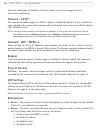
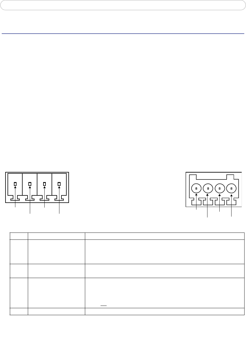
The I/O Terminal Connector
Pinout and Interface
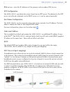
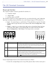
The 4-pin I/O terminal connector provides the interface to:
• 1 transistor output
• 1 digital input
• auxiliary power and GND
The terminal connector is used in applications fo
r e.g. motion detection, event triggering,
time lapse recording, alarm notification via e-mail, image storage to FTP locations, etc.
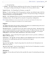
• Input - for connecting e.g.
a push button. If the push button is pressed, the state
changes and the input becomes active (shown under Event Configuration > Port
Status).
• Output - connects
e.g. an alarm device that can be activated by Output buttons
on the Live View page, or by an Event Type. The output will show as active
(Event Configuration > Port Status) if the alarm device is activated.
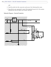
Connect input/output devices to the ter
minal connector as follows:
1. Loosen the corresponding screw on top of the pin (see above
for the correct pin to
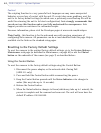
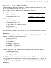
Pin Function Description
4 Transistor Output With a maximum load of 100mA and a max
imum voltage of 24V DC, this output
has an open-collector NPN transistor with the emitter connected to pin 1 (GND).
If used with an external relay, a diode must be connected in parallel with the load,
for protection against voltage transients.
3 Digital Input Connect to GND to activate, or leave flo
ating (or unconnected) to deactivate.
2 Auxiliary DC Power Input 7-20 VDC/max 5W. Electrically connected in pa
rallel with the PS-K power
connector, this pin provides an auxiliary connector for mains power to the unit. If
the unit is powered via this pin, a fuse should be used (rating: 1A Slow).
This pin can also be used to power auxiliar
y equipment, max 100mA, but note that
this is
not possible when the AXIS 211 is powered by PoE.
1 GND
Pin 4
Pin 3
Pin 2
Pin 1
Pin 4
Pin 3
Pin 2
Pin 1