


63
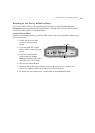
AXIS 243SA - Unit connectors
Y/C to BNC cable
AXIS 243SA supports conversion from Y/C (S-video) to composite video using an Y/C to
BNC cable. The cable is available as an accessory - see the Axis Web site at:
www.axis.com. Follow these instructions to connect the Y/C to BNC cable:
1. Connect the BNC connector marked IN to the Vide
o In connector on the video
server.
2. Connect the BNC connector marked OUT to the Video OUT connector on the
video server.
3. Connect the Y/C connector to the Y/C video unit (S-video).
4. Set the DIP switches on the front panel of the unit to 1=ON, 2=ON, 3=OFF,
4=OFF.
5. Go to AXIS 243SA web pages under Setup > Video & Image > Video Source and
select Y/C (S-video) from the Physical connector drop-down list.
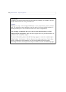
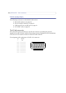
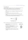
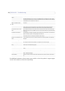
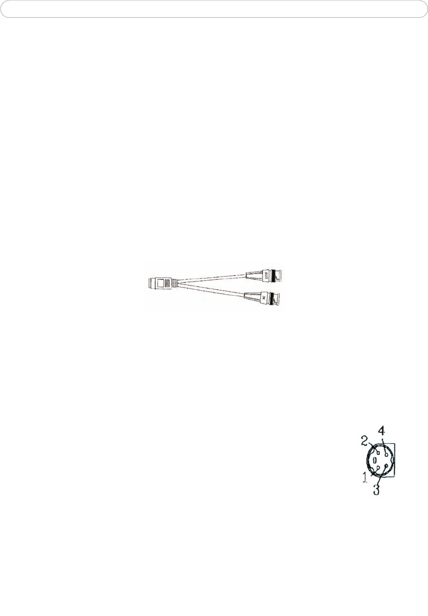
One female MiniDin 4-pol connector
split into two BNC connectors
Below is a description of how the cable can be assembled using standard components:
1. Use two male BNC connectors and one female 4-pole
Min
iDin connector.
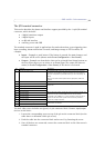
2. Connect pin 1, 2 and shield on the MiniDin connector to
the shield on the two BNC connectors.
3. Connect pin 3 (Y) on the MiniDin connector to centre pin
on one of the male BNC connectors, mark this BNC
connector with IN.
4. Connect pin 4 (C) on the MiniDin connector to centre pin
on the other male BNC connector, mark this BNC connector
with OUT.
The pins on the
MiniDin connector