


9
AXIS 243SA - Product description
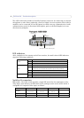
Note: • If the video source is to be connected in parallel with other equipment, disable the
input termination by turning the corresponding DIP switch to the up position (OFF). Failure
to do so may cause reduced image quality.
• The AXIS 243SA
supports conversion between composite video and Y/C (S-Video) using
a Y/C to BNC cable (not supplied).
Control Button - Press this button to restore the factory default settings, as described in
Resetting to the factory default settings,
on page 59, or to install the video server using
AXIS Internet Dynamic DNS Service (See the
Axis Video Server Installation Guide).
Video Input - The
video input is connected using a coax/BNC connector. Physical
connections made using 75 ohm coaxial video cable have a recommended maximum
length of 800 feet (250 meters).
Video Output - Loop-through co
nnection to the video signal from the Video In connector.
Terminated with a coaxial/BNC connector. Allows direct connection of an external monitor
for example. Set DIP switch to OFF when in use.
Line Out - Mono
audio output (line level), which can be connected to a public address (PA)
system or an active speaker with a built-in amplifier. A pair of headphones can also be
attached.
Line/Mic In - Sin
gle 3.5 mm input for a mono microphone, or line level mono signal (only
the left channel is used from a stereo signal).
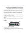
Rear panel
Power adapter connector - For connection of the power adapter.
I/O terminal connector
- The I/O terminal connector provides the physical interface to one
digital transistor output, one digital input, and an RS-485 interface. See Unit connectors,
on page 60 for more information.
Note:
The I/O terminal connector also provides an auxiliary connection point for DC power.
Power adapter
connector
12-pin I/O terminal
connector
RS-232
connector
Network
connector
Serial number on underside label