


49
AXIS 214 PTZ - Connections
Connections
I/O inputs and outputs
The 4-pin I/O terminal connector provides the interface to:
• 1 transistor output
• 1 digital input
• auxiliary power and GND
The I/O terminal connector is used in applications for e.g. motion detection, event
triggering, time lapse recording, alarm notification via email, image storage to FTP
locations, etc.
• Input - for connecting e.g. a push button. If the push button is pressed, the state
changes and the input becomes active (shown under Event Configuration > Port
Status).
• Output - connects e.g. an alarm device that can be activated by Output buttons
on the Live View page, or by an Event Type. The output will show as active
(Event Configuration > Port Status) if the alarm device is activated.
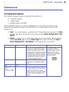
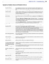
Function Pin no. Description Pinouts
Transistor Output Pin 4 With a maximum load of 100mA and
a maximum voltage of 24V DC, this
output has an open-collector NPN
transistor with the emitter connected
to the GND pin. If used with an exter
-
nal relay, a diode must be connected
in parallel with the load, for protec
-
tion against voltage transients.
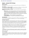
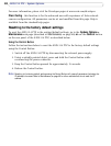
The I/O terminal pins on
the AXIS 214 PTZ are
numbered right to left, as
shown here. This is the
view when the camera is
ceiling mounted.
4
1
Digital Input Pin 3 Connect to GND to activate, or leave
floating (or unconnected) to deacti-
vate.
GND Pin 2
Auxiliary DC Power
Input
(12VDC min 12W)
Pin 1 Connected electrically in parallel with
the power adapter, this pin provides
an auxiliary connector for mains
power to the unit. It can also be used
to power auxiliary equipment, max
50mA.