


7
AXIS 214 PTZ - Product Description
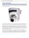
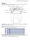
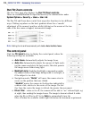
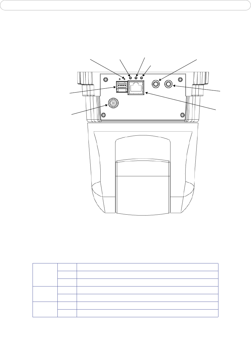
Rear panel
The rear panel contains all of the connections available on the AXIS 214 PTZ. The view
shown here is from a ceiling mounted camera.
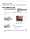
Line/Mic in
Line out
Network
Power connector
I/O terminal connector
Status indicator
Network indicator
Power indicator
Control button
connector
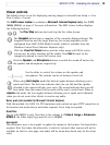
Control button - This is used to restore the factory default settings, as described in Resetting
to the factory default settings, on page 48.
Indicators - After completion of the startup and self-test routines, the multi-colored
Network, Status and Power indicators flash as follows:
Amber Flashes for activity on a 10 Mbit/s network
Green Flashes for activity on a 100 Mbit/s network
None No connection
Green Normal operation
Amber Flashes during startup, reset to factory default and firmware upgrade
Green Normal operation
Amber Flashes green/amber during upgrade
I/O Terminal connector - The I/O terminal connector provides the physical interface to one
transistor output, one digital input and an auxiliary connection point for DC power. For
more information, see
I/O inputs and outputs, on page 49.
Network
Status
Power