


AXIS P5522 PTZ Dome Network Camera
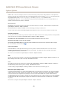
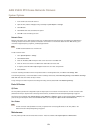
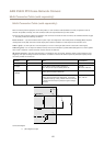
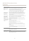
Multi-Connector Cable (sold separately)
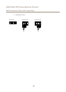
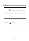
Multi-Connector Cable (sold separately)
When connecting external equipment to the Axis product, a multi-connector cable (available from Axis) is required in order to
maintain the product’s IP rating. The multi-connector cable can be purchased from your Axis reseller.
Connect the multi-connector cable to the product’s multi-connector. To locate the multi-connector, see Hardware Overviewon page
7 . The cable provides the following connectors:
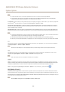
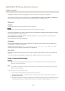
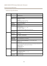
Power connector - 3-pin terminal block used for power input. See image below. Use a Safety Extra Low Voltage (SELV) compliant
limited power source (LPS) with either a rated output power limited to ≤100 W or a rated output current limited to ≤5 A.
Audio in (pink) - 3.5 mm input for a mono microphone, or a line-in mono signal (left channel is used from a stereo signal).
Audio out (green) - 3.5 mm output for audio (line level) that can be connected to a public address (PA) system or an active speaker
with a built-in amplier. A stereo connector must be used for the audio out.
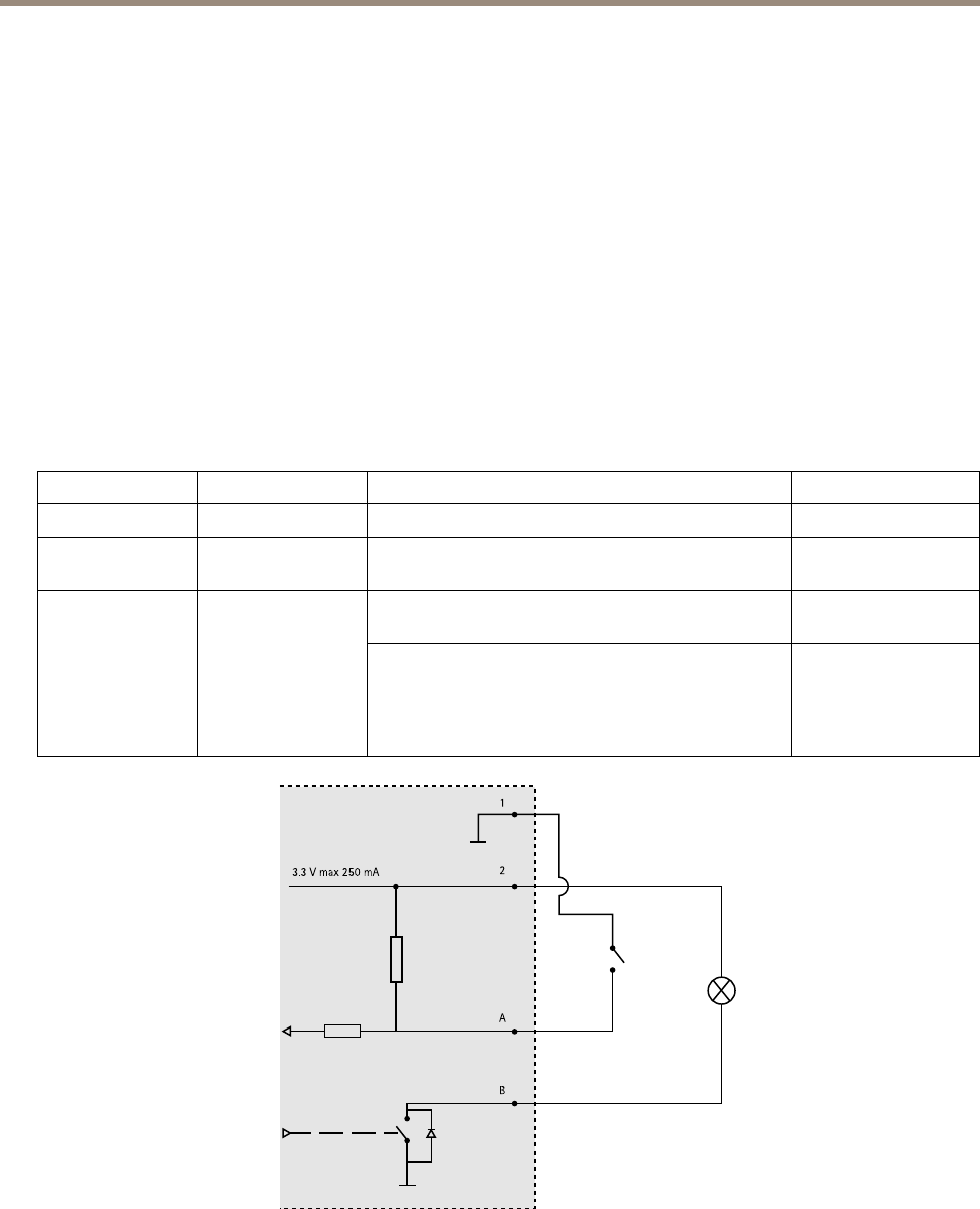
I/O terminal connector - Use with external devices in combination with, for example, tampering alarms, motion detection, event
triggering, time lapse recording and alarm notications. In addition to the 0 V DC reference point and power (DC output), the I/O
connector provides the interface to:
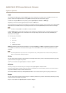
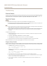
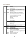
Function Pin Notes
Specications
0 V DC (-)
1
DC output
2
Can be used to power auxiliary equipment.
Note: This pin can only be used as power out.
3.3 V DC
Max load = 250 mA
Digital input – Connect to pin 1 to activate, or leave
oating (unconnected) to deactivate.
0 to max 40 V DC
Congurable (Input
or Output)
3–6
Digital output – Connected to pin 1 when activated,
oating (unconnected) when deactivated. If used with
an inductive load, e.g. a relay, a diode must be connected
in parallel with the load, for protection against voltage
transients.
0 to max 40 V DC, open
drain, 100 mA
3.3 V max 250 mA
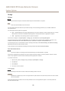
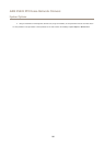
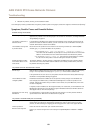
1
2
A
B
Connection diagram
A
I/O congured as input
57