


AXIS Q3505–V Fixed Dome Network Camera
Technical Specifications
Function/group
Item
Specications
Optional
accessories
AXIS Intrusion Switch B
Axis T90A Illuminators
AXIS T91A/B Mounting Accessories
AXIS Conduit Adapter U-Shape 20mm A
AXIS T94K01D Pendant Kit
AXIS T94K01L Recessed Mount
AXIS Microphone kit A
AXIS Skin Cover A (5 nos.)
Smoked Dome
Warranty
Axis 3-year warranty and AXIS Extended Warranty option, see www.axis.com/warranty
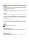
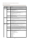
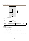
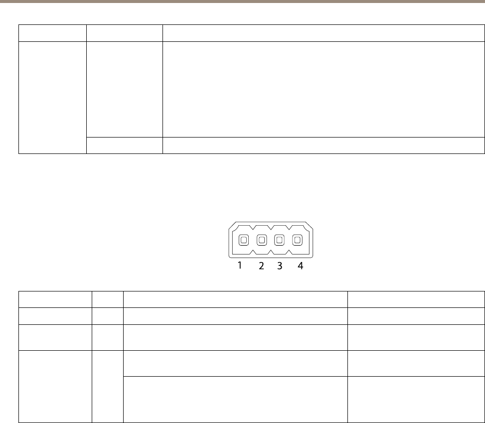
Connectors
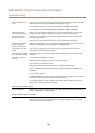
I/O Connector
4–pin terminal block for:
• Auxiliary power (DC output)
• Digital Input
• Digital Output
• 0 V DC (-)
1
2 3 4
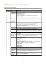
Function Pin Notes
Specications
0 V DC (-)
1
0 V DC
DC output
2
Can be used to power auxiliary equipment.
Note: This pin can only be used as power out.
12 V D C
Max load = 50 mA
Digital input – Connect to pin 1 to activate, or leave oating
(unconnected) to deactivate.
0 to max 30 V DCCongurable
(Input or Output)
3–4
Digital output – Connected to pin 1 when activated, oating
(unconnected) when deactivated. If used with an inductive
load, e.g. a relay, a diode must be connected in parallel with
the load, for protection against voltage transients.
0 to max 30 V DC, open drain,
100 mA
65