


AXIS Q3505–V Fixed Dome Network Camera
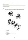
Hardware Overview
12.
Camera unit
13.
Dome cover
14.
Springs in unit casing
15.
Status LED
16.
Function button
Connectors and Buttons
For technical specications, see page 62.
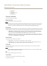
Network Connector
RJ45 Ethernet connector with Power over Ethernet (PoE).
NONO
NO
TICETICE
TICE
The product shall be connected using a shielded network cable (STP). All cables connecting the product to the network shall
be intended for their specic use. Make sure that the network devices are installed in accordance with the manufacturer’s
instructions. For information about regulatory requirements, see Electromagnetic Compatibility (EMC) on page 2 .
I/O Connector
Use with external devices in combination with, for example, tampering alarms, motion detection, event triggering, time lapse recording
and alarm notications. In addition to the 0 V DC reference point and power (DC output), the I/O connector provides the interface to:
• Digital output – For connecting external devices such as relays and LEDs. Connected devices can be activated by the
VAPIX® Application Programming Interface, output buttons on the Live View page or by an Action Rule. The output will
show as active (shown under System Options > Ports & Devices) if the alarm device is activated.
• Digital input – An alarm input for connecting devices that can toggle between an open and closed circuit, for example:
PIRs, door/window contacts, glass break detectors, etc. When a signal is received the state changes and the input becomes
active (shown under System Options > Ports & Devices).
Audio Connector
The Axis product has the following audio connectors:
• Audio in (pink) – 3.5 mm input for a mono microphone, or a line-in mono signal.
• Audio out (green) – 3.5 mm output for audio (line level) that can be connected to a public address (PA) system or an
active speaker with a built-in amplier. A stereo connector must be used for audio out.
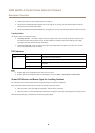
SD Card Slot
A microSD card (not included) can be used for local recording with removable storage. For more information, see Technical
Specications on page 62.
NONO
NO
TICETICE
TICE
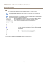
To prevent corruption of recordings, the SD card should be unmounted before removal. To unmount, go to Setup > System
Options > Storage > SD Card and click Unmount.
Note
For SD card recommendations see www.axis.com
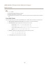
Control Button
For location of the control button, see Hardware Overview on page 6 .
The control button is used for:
7