


The I/O Terminal Block Connector AXIS 2130/2130R User’s Manual
34
Appendix E - The I/O Terminal Block Connector
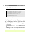
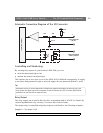
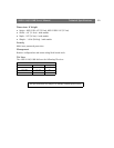
A 4-pole connector is provided for external I/O connections to the AXIS 2130/2130R. The
connector provides the interface to a single output and a single input. A diagram for the
connector, complete with a pinout table is provided below.
Input
Used for connecting external alarm devices and triggering images for specific alarm-based
events, the input is typically connected to a motion detector - or any other external
security device - for saving images on each occasion the detector is activated.
Output
The output can drive a maximum load of 50V DC at 100mA directly, and by connecting
additional relay circuitry, it can drive even heavier loads. If the output is used with an
external relay, a diode must be connected in parallel with the load for protection against
any voltage transients.
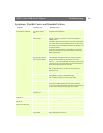
Pins Function
OUT A
OUT B
The two external device output terminals (A and B) are automatically switched to the
connected or disconnected postion - there is no distinction between + and -. The terminals
use optocouplers and are electrically insulated from the other internal circuitry.
The maximum load should not exceed 100mA and the maximum voltage should be no
higher than 50V DC. Note: Connecting AC to the output will damage the unit.
IN+
IN -
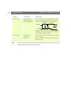
The external device input terminals consist of a + terminal and a - teminal. The - terminal is
grounded on the inside of the main unit. Interupts are generated by connecting cables to
the terminals and shorting (ON) or breaking (OFF) the circuit. Sensors and switches should
be connected to these terminals with electrically isolated GND and power supplies.
_
+
B
A