


High Speed Pan/Tilt System Configuring the Device | en 25
Bosch Security Systems Instruction Manual F01U.073.990 | Version 1.0 | 2007.07
7 Configuring the Device
Before powering the High Speed Pan/Tilt, it must be properly configured. To configure the DIP
switches inside the configuration window, proceed as follows:
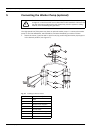
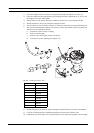
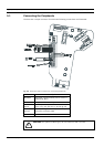
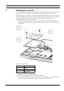
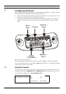
1. Open the configuration window by unscrewing the screws with a 3 mm Allen wrench. See
Figure 6.3 for the location of the configuration window.
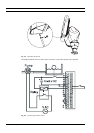
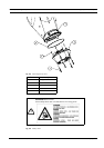
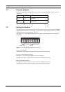
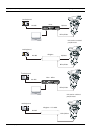
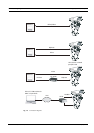
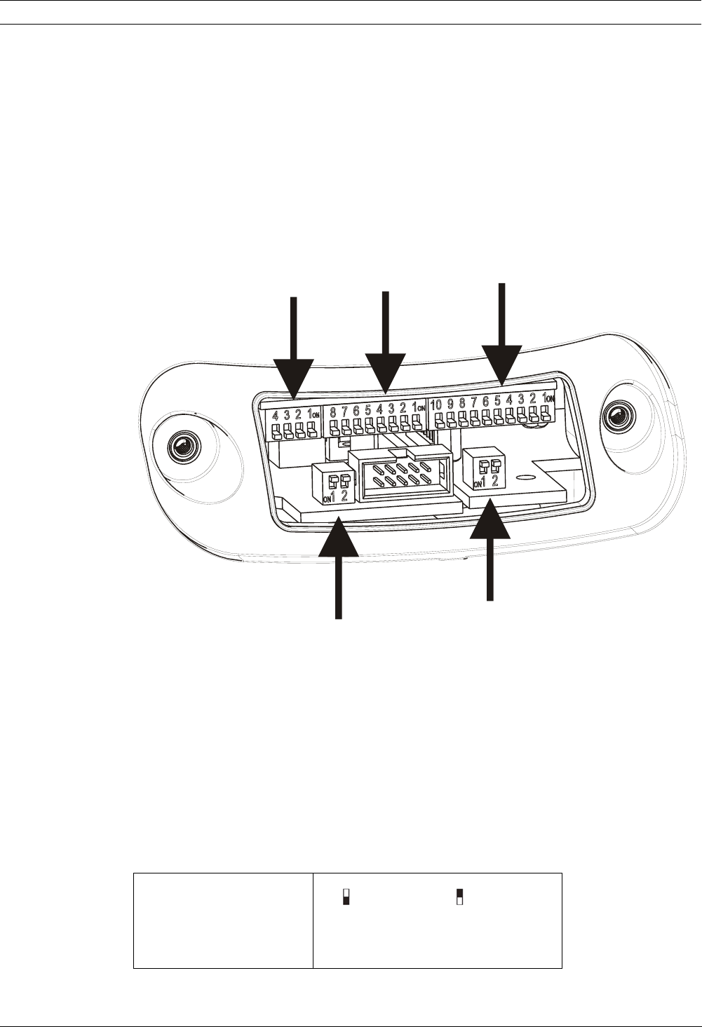
2. Verify that the position of the DIP switches are the same as in Figure 7.1. Starting from
the left, we see the baud rate, protocol, and the peripheral address selectors, respec-
tively.
Fig. 7.1 Positioning the DIP Switches
For all DIP switches, when the rocker is down the switch is OFF, or represents the logical
value “0”; when the rocker is up, the switch is ON, with logical value “1”. The white rectangle
represents the position of the rocker.
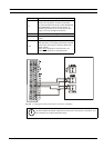
7.1 Baud Rate Switches
DIP switches 4, 3, and 2 are not used; the unit has fixed baud rates. DIP switch No. 1 is used
to update the firmware: PROGRAM. ON and PROGRAM. OFF. During normal use, make sure
the rocker for DIP switch No. 1 is OFF (PROGRAM. OFF).
Baud
Rate
Protocol
A
ddress +
Serial
Rs485
Terminations
Biphase +
Bilinx
DIP-SWITCH 1
(for updating the firmware)
Table 7.1 Updating the Firmware
Program ON
Program OFF