


VIP XD Operation | en 59
Bosch Security Systems Installation and Operating Manual DOC | V4.0 | 2009.06
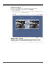
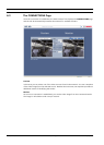
6.4 Hardware Connections Between Video Servers
You can easily connect a VIP XD with a connected monitor as a receiver, together with a
compatible sender (for example VIP X1600) with a connected camera via an Ethernet
network. In this way it is possible to cover long distances without the need for major
installation or cabling work.
Installation
Compatible video servers are designed to connect to one another automatically, provided
they are correctly configured. They only need to be part of a closed network. Proceed as
follows to install the units:
1. Connect the units to the closed network using Ethernet cables.
2. Connect them to the power supply.
Connecting
There are three options for establishing a connection between a sender and a compatible
receiver in a closed network:
– an alarm,
– a terminal program, or
–Internet Explorer.
Connecting on Alarm
With the appropriate configuration, a connection between a sender and a receiver is made
automatically when an alarm is triggered (see Section 5.11 Alarm Connections, page 34). After
a short time the live video image from the sender appears on the connected monitor.
This option can also be used to connect a sender and a compatible receiver using a switch
connected to the alarm input. You do not need a computer to make the connection in this
case.
Connecting with a Terminal Program
Various requirements must be met in order to operate with a terminal program (see
Section 8.7 Communication with Terminal Program, page 67).
1. Start the terminal program and enter the command 1 in the main menu to switch to the
IP menu.
2. Enter the command 4 in the IP menu to change the remote IP address, then enter the IP
address of the unit you wish to connect to.
3. Enter the command 0 to return to the main menu and then enter the command 4 to
switch to the Rcp+ menu.
4. In the Rcp+ menu, enter the command 5 to activate the automatic connection.
Closing the Connection with a Terminal Program
1. Start the terminal program and enter the command 4 in the main menu to switch to the
Rcp+ menu.
2. In the Rcp+ menu, enter the command 5 to deactivate the automatic connection.
i
NOTICE!
The sender and receiver must be located in the same subnet to establish a hardware
connection.
i
NOTICE!
Make sure that the units are configured for the network environment and that the correct IP
address for the remote location to be contacted in the event of an alarm is set on the Alarm
Connections configuration page (see Section 5.11 Alarm Connections, page 34).