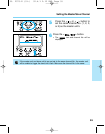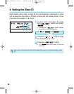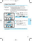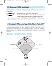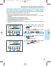
2. Wireless E-TTL Autoflash With Flash Ratio ON
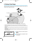
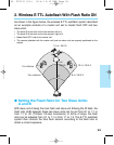
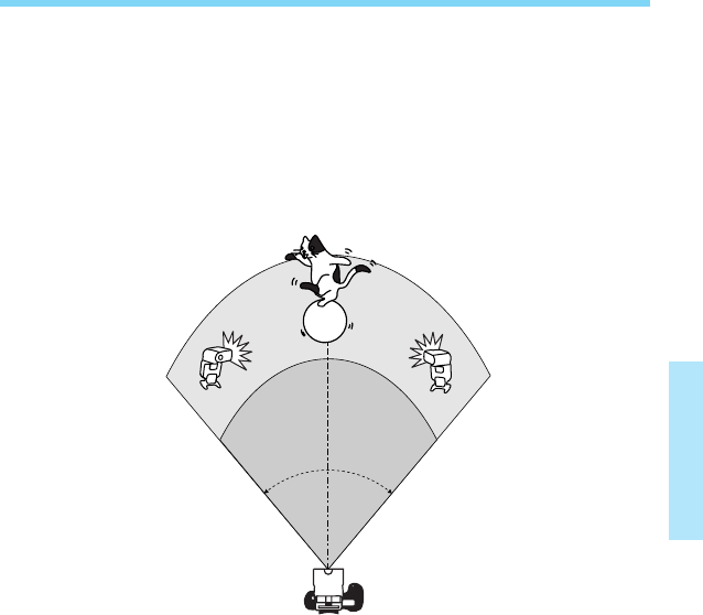
As shown in the figure below, the wireless E-TTL autoflash system described
as an example consists of a master unit set to master flash OFF and two
slave units.
• The slave ID of the slave unit on the camera’s left is A.
• The slave ID of the slave unit on the camera’s right is B.
• Master flash OFF is set for the master unit.
• The camera (attached with the master unit) and two slave units are properly positioned for the
subject.
63
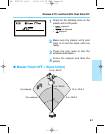
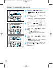
● Setting the Flash Ratio for Two Slave Units:
A and B
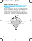
With slave unit A being the main flash and slave unit B being the fill flash, the
flash ratio (A:B) between these two slave units can be set from 8:1 to 1:1 or
from 1:1 to 1:8. (Thirteen 1/2-stop increments.) In terms of stops, the flash
ratio can be adjusted from 3:1 to 1:1 or from 1:1 to 1:3. The E-TTL autoflash
system then controls the total flash amount according to the flash ratio to
obtain a correct exposure.
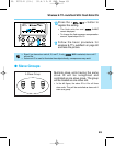
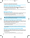
For indoors
For outdoors
15 m / 49.2 ft
10 m /
32.8 ft
12 m / 39.4 ftBA
8 m / 26.2 ft
80°
05. F073-E (51~) 02.4.1 2:12 PM Page 63


