


REMOTE UNIT INSTALLATION
Digimerge Dialup Video Server User’s Guide
10
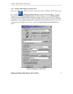
Phone connector on the DVS. In that case, you may need to adjust (increase) the number of
rings after which the DVS will respond to an incoming call in order to avoid conflicts with
normal phone and/or fax usage and the associated inconveniences. See section 5.2.1 and
Figure 7 on page 23 for more information on DVS configuration options.
Note: The condition of the telephone line could be a reason for low modem connection
rate and poor image transmission performance. We recommend you to avoid
connecting DVS through PBX boxes because the reduced voltage may interfere
with connection reliability. We also suggest that you use a direct telephone line
connection to hook up the DVS unit. Finally, since the DVS system is designed for
in-door use, it should not be installed in places with high humidity or extreme
temperature variation.
• Next, connect one or more video cameras to any of the 4 BNC connectors on the back panel
of the DVS box. DVS is capable of camera auto-detection so you are free to use any of the
unit’s video inputs in any order. You may also safely mix color and black & white cameras,
as long as they all conform to the same electrical and video standard (NTSC or PAL).
However, mixture not recommended because of possible video synchronization problems.
Then power on the cameras.
• Finally, after all other connections are completed, connect the power supply cord (DC 12V
1.2A) to the corresponding socket on the DVS unit.
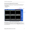
Immediately after the power is supplied to the DVS unit, the board starts the internal self-test.
Test progress is always shown on the front LEDs. There are 2 LEDs: POWER (yellow) and
ACTIVE (green). The LEDs will behave in the manner as described below during power up
sequence:
Test (power-up) behavior of DVS unit.
1. ACTIVE (green) and POWER (yellow) turn on together, then ACTIVE (green) turns
off.
2. POWER (yellow) during the whole test will indicate test progress step by step by
turning off for a short time at the beginning of each step 13 times.
3. When the test successfully passes, POWER (yellow) remains lit and the ACTIVE
(green) starts blinking 2 times per second (status is disconnected).
4. When the DVS detects a connection, the ACTIVE (green) light will blink at double the
rate it blinks in the disconnected state.
If these steps do not occur with your system, disconnect and reconnect the power and try again.
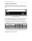
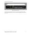
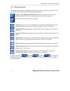
The detailed layout of DVS connectors are shown in Figure 2. It is very simple and well
inscribed.