


18
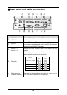
Pin No. Name Pin No. Name Pin No. Name
1 Video signal (Red) 6 GND (Red) 11 GND
2 Video signal (Green) 7 GND (Green) 12 N.C
3 Video signal (Blue) 8 GND (Blue) 13
Horizontal
synchronized signal
4 N.C 9 N.C 14
Vertical
synchronized signal
5 GND 10 GND 15 N.C
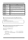
③ To connect the unit to a device (audio amplifier etc) with an audio line output
terminal.
Connect a commercially available audio cable to the [AUDIO IN] terminal on the rear panel.
④ To switch the output image type.
Change the output image type.
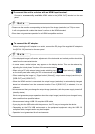
⑤ To connect the unit to a device with Ethernet terminal.
Connect the supplied LAN cable to the [Ethernet terminal] terminal on the rear panel.
Explanation of the Ethernet terminal LED
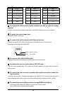
⑥ To connect a PC with the USB cable.
Connect the supplied USB cable to the [USB] terminal on the rear panel.
⑦ To connect the unit to a device with an RS-232C port.
The unit can be controlled from a PC through an RS-232C cable by using [RS-232C] terminal on
the rear panel.
⑧ To connect the unit to a device (speaker with amplifier etc) with an audio line
input terminal.
Connect a commercially available audio cable to the [AUDIO OUT] terminal on the rear panel
after looping the audio cable 2 times around the ferrite core that is supplied with this product.
⑨ To connect the unit to a device with an analog RGB input terminal.
Connect the RGB cable to the [RGB OUT] terminal on the rear panel.
Only 1 RGB cable is supplied with the product.
Orange…Blinking: Access
Green … ON: Link OK