


11
English
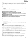
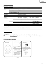
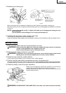
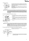
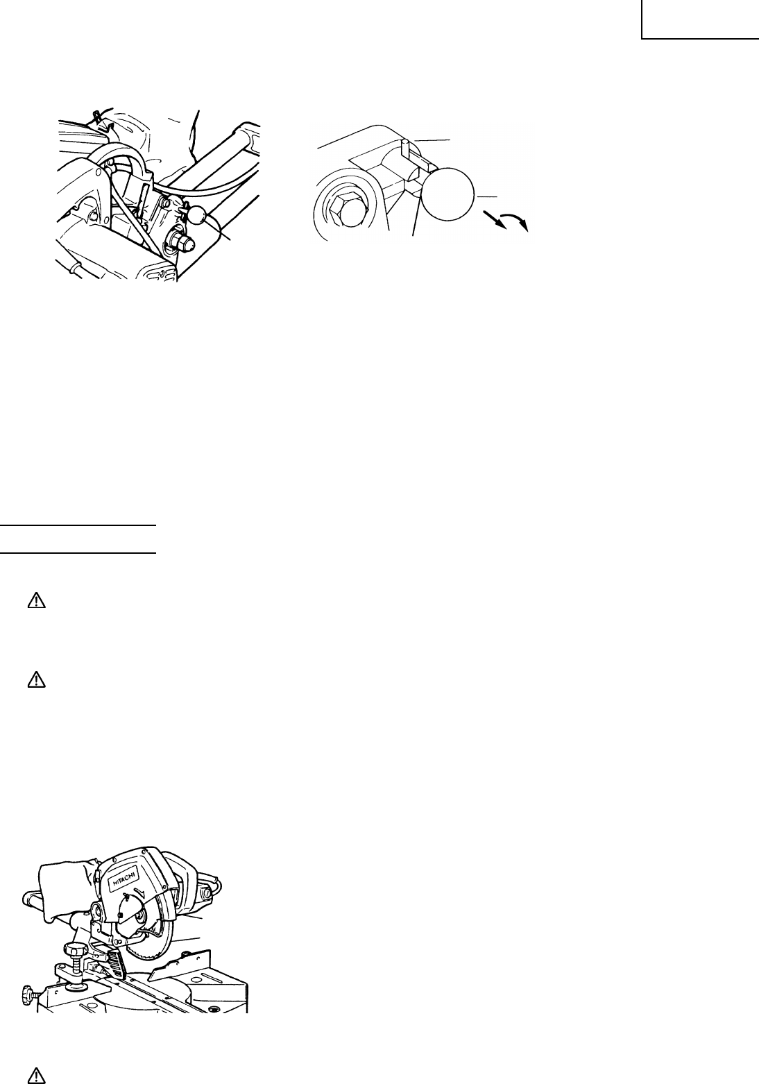
2. Releasing the locking pin
Fig. 6-a Fig. 6-b
When the power tool is prepared for shipping, its main parts are secured by a locking pin.
Move the handle (see Fig. 1) slightly so that the locking pin can be disengaged and adjusted as indicated
in Fig. 6-b.
NOTE: Lowering the handle (see Fig. 1) slightly will enable you to disengage the locking pin more
easily and safely.
The lock position of the locking pin is for carrying and storage only.
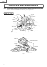
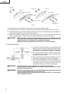
3. Installing the dust bag, holder, stopper and vises.
(The holder and stopper are optional accessories).
Attach the dust bag, holder, stopper and vise assembly, slide fence (A) and slide fence (B) as indicated in Fig. 1.
BEFORE USING
1. Make sure the power source is appropriate for the tool.
WARNING: Never connect the power tool unless the available AC power source is of the same
voltage as that specified on the nameplate of the tool.
Never connect this power tool to a DC power source.
2. Make sure the trigger switch is turned OFF.
WARNING: If the power cord is connected to the power source with the trigger switch turned
ON the power tool will start suddenly and can cause a serious accident.
3. Check the saw blade for visible defects.
Confirm that the saw blade is free of cracks or other visible damage.
4. Confirm that the saw blade is attached securely to the power tool.
Using the supplied 10mm box wrench, tighten the bolt on the saw blade spindle to secure the saw blade.
For details, see Fig. 37-a and Fig. 37-b in the section on “SAW BLADE MOUNTING AND DISMOUNTING”.
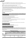
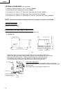
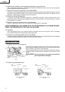
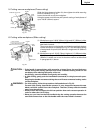
5. Check the safety cover for proper operation.
Safety cover is designed to protect the operator from coming into
contact with the saw blade during operation of the tool.
Always check that the safety cover moves smoothly and covers
the saw blade properly.
Fig. 7
WARNING: NEVER OPERATE THE POWER TOOL if the safety cover does not function smoothly.
During transport, fit the pin into the
deep slot.
NOTE: This position is not be used
for any cutting operation.
Locking Pin
During operation fit
the pin stoppers into
the shallow slot.
Pull out to disengage.
Rotate the knob 1/4 turn
and fit the pin stoppers
into the shallow slot.
Clockwise
Locking Pin
Safety Cover
Sub Cover