


20
English
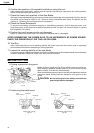
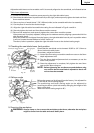
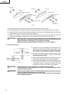
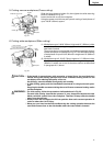
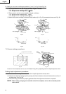
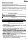
(2) Setting to cut crown moldings at positions w and e in Fig. 28 (see Fig. 31):
q Turn the turntable to the left and set the Miter Angle as follows:
* For 45°type crown moldings: 35.3° ( mark)
* For 38°type crown moldings: 31.6° ( mark)
w Tilt the head to the left and set the Bevel Angle as follows:
* For 45°type crown moldings: 30° ( mark)
* For 38°type crown moldings: 33.9° (
mark)
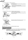
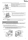
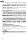
e Position the crown molding so that the lower surface (B in Fig. 27) contacts the fence as in Fig. 32.
Fig. 29 Fig. 31
Fig. 30 Fig. 32
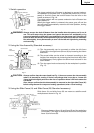
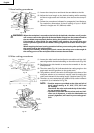
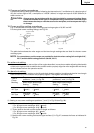
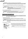
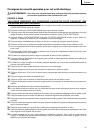
11. Groove cutting procedures
Fig. 33 Fig. 34
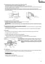
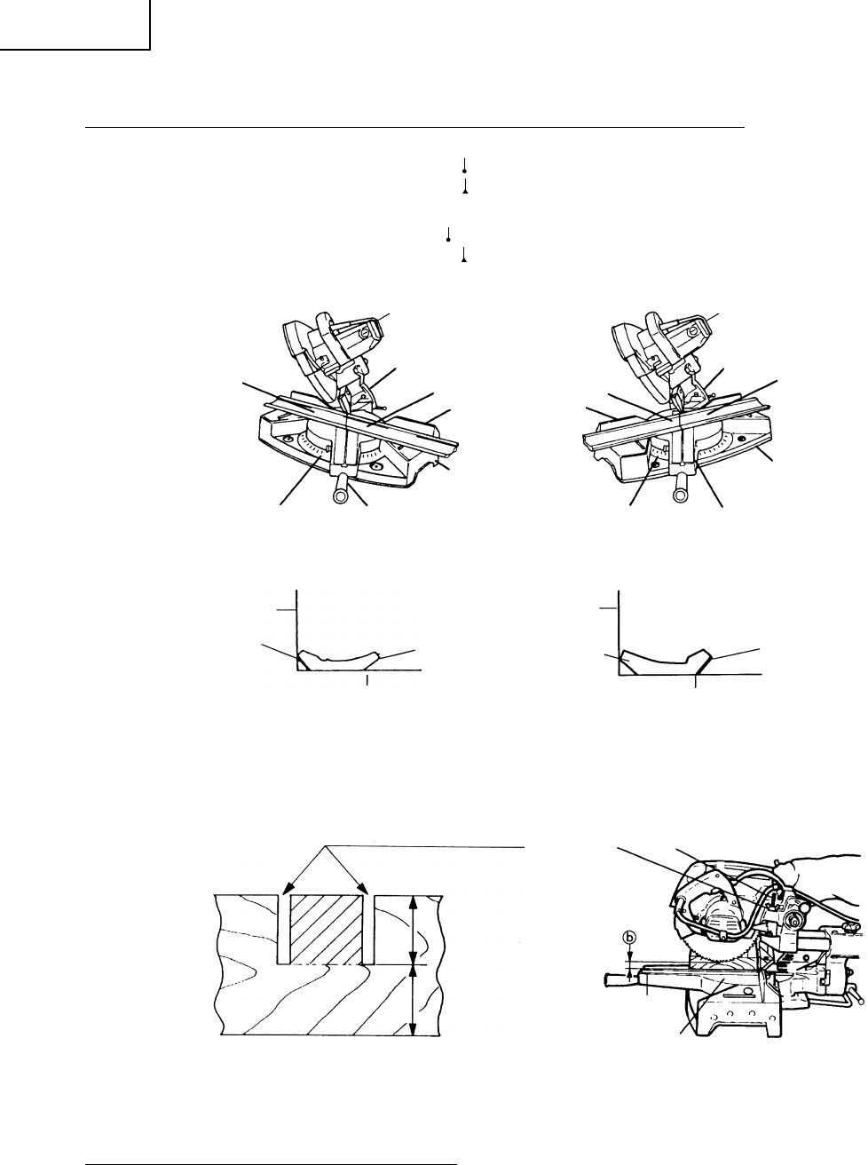
Grooves in the workpiece can be cut as indicated in Fig. 33 by adjusting the 8mm depth adjustment bolt.
Cutting depth adjustment procedure:
(1) Loosen the 8mm wing nut and turn the 8mm depth adjustment bolt by hand.
(2) Adjust to the desired cutting depth by setting the distance between the saw blade and the surface of
the base (see b in Fig. 33).
(3) The 8mm wing nut must be properly tightened after the adjustment has been completed.
NOTE: When cutting a single groove at either end of the workpiece, remove the unneeded portion
with a chisel.
Fence
Table on Base
B
Table on Base
Fence
A
B
A
q
Bevel
Angle Scale
r
Fence
Base
Miter Angle Scale
Turntable
Bevel
Angle Scale
e
Base
Miter Angle Scale
Fence
w
Turntable
Head
Head
Bottom Line of
the Groove
Turntable
a
b
Cut grooves with saw blade
8mm
Wing Nut
8mm
Depth Adjustment Bolt