


15
English
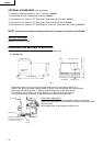
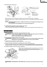
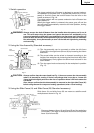
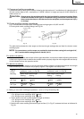
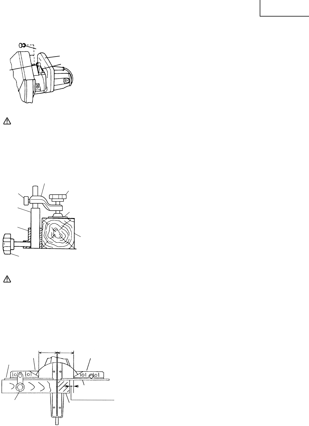
Fence (B)
Slide Fence (B)
Workpiece
2-5/32" (55mm)2-4/3" (70mm)
Fence (A)
Slide Fence (A)
Cut off side piece
Fig. 18
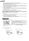
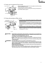
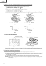
Handle
Lock-off Button
Hole
Trigger Switch
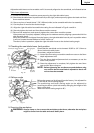
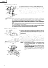
Knob
Vise Plate
Workpiece
10mm Knob Bolt
Fence
Vise Shaft
Screw Holder
Clearance between fence (A) and fence (B) and the workpiece
is necessary. The edge of workpiece should not overlap with
fence (A) and fence (B).
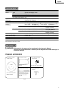
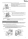
1. Switch operation
The trigger switch lock-off button is designed to prevent inadvert-
ent operation of the power tool. To operate the power tool, it is nec-
essary to first fully insert the lock-off button into the hole on the
handle as shown in Fig. 16.
The trigger switch will not operate unless the lock-off button has
been pushed in.
When the trigger switch is released, the power goes off and the
lock-off button automatically returns to its initial position, locking
the trigger switch.
Fig. 16
WARNING: Always remove the lock-off button from the handle when the power tool is not in
use. This will ensure that the power tool cannot be turned on accidentally or by
someone (especially a child) who is not qualified to use the power tool. If the lock-off
button is left in the handle, serious personal injury can result. Since the lock-off button
fits rather tightly, it may be necessary to turn it to the left and right during mounting
and removing.
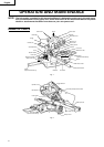
2. Using the Vise Assembly (Standard accessory)
(1) The vise assembly can be mounted on either the left fence
{Fence (B)} or the right fence {Fence (A)} by loosening the 10mm
knob bolt.
(2) The screw holder can be raised or lowered according to the
height of the workpiece by loosening the 6mm knob bolt. After
the adjustment, firmly tighten the 6mm knob bolt and fix the
screw holder.
(3) Turn the upper knob and securely fix the workpiece in position
(Fig. 17).
CAUTION: Always confirm that the motor head (see Fig. 1) does not contact the vise assembly
when it is lowered for cutting. If there is any danger that it may do so, loosen the
10mm knob bolt slightly and move the vise to a position where it will not contact the
saw blade.
Also, always confirm that the vise assembly is mounted on the right side {Fence (A)}
before using the saw for compound cutting operations (miter + bevel cutting).
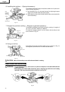
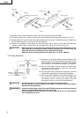
3. Using the Slide Fence (A) and Slide Fence (B) (Standard accessory)
Slide fence (A) and slide fence (B) are meant to stabilize small
workpieces as shown in Fig. 18.
6mm
Knob Bolt
Fig. 17