


8
English
OPERATION AND MAINTENANCE
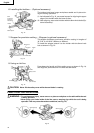
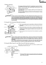
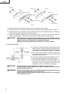
NOTE: The information contained in this Instruction Manual is designed to assist you in the safe opera-
tion and maintenance of the power tool. Some illustrations in this Instruction Manual may show
details or attachments that differ from those on your own power tool.
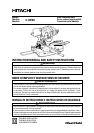
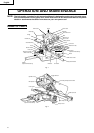
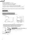
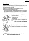
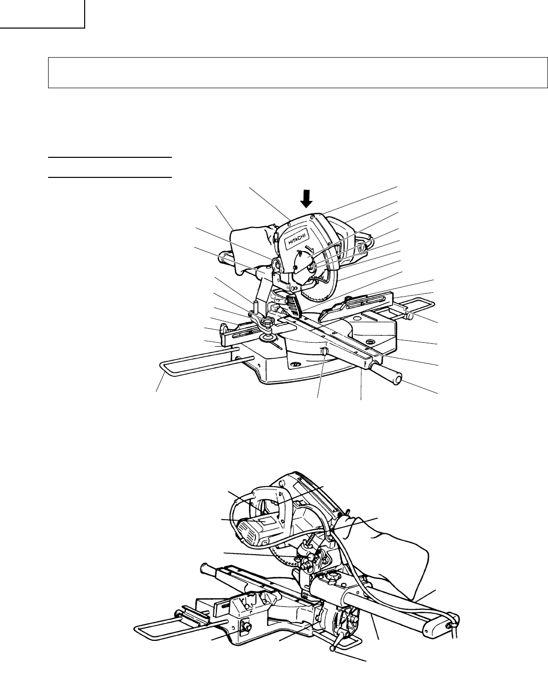
NAME OF PARTS
Fig. 1
Fig. 2
Trigger Switch
8mm Depth Adjustment Bolt
Slide Pipe (B)
Slide Pipe (A)
Clamp Lever
Indicator
6mm Knob Bolt
(Optional Accessory)
Locking Pin
Nameplate
Spindle Lock
Fence (A)
Slide Fence (A)
Stopper
(Optional Accessory)
Table Insert
Turntable
Indicator
Saw Cover
Slide Fence (B)
10mm Knob Bolt
Fence (B)
Screw Holder
Vise Assembly
Holder
(Optional Accessory)
Gear Case
Base
Side Handle
Dust Bag
Knob
Holder (A)
Hinge
Handle
Spindle Cover
Bolt
Washer (C)
Sub Cover
Safety Cover
Guard
Head