


16
English
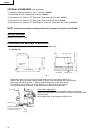
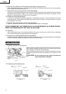
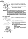
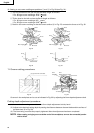
Fig. 19
(1) Set slide fence (A) and slide fence (B) on fence (A) and fence (B) of the base.
(2) To attach use the four machine screws with nylon washers and flange nuts as shown in Fig. 19.
(3) Adjust slide fence (A) and slide fence (B) to stabilize the workpiece. Adjustable range of slide fence
(A) and slide fence (B) is from 0 to 3-3/4" (0 to 95mm)).
(4) Confirm the position of slide fence (A) and slide fence (B) on fence (A) and fence (B) with four
machine screws tightly so slide fence (A) and slide fence (B) do not move (see Fig. 19).
CAUTION: * Before operation, ensure that the saw blade does not contact slide fence (A) and
slide fence (B). In case the saw blade contacts slide fence (A) and slide fence (B),
adjust the position of slide fence (A) and slide fence (B) again.
* Maximum cross-cutting width (Bevel 0°, Miter 0°) is 11-21/32" (296mm).
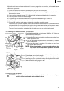
4. Cutting Operation
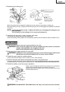
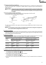
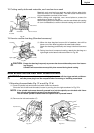
(1) As shown in Fig. 20 the width of the saw blade is the
width of the cut. Therefore, slide the workpiece to the
right (viewed from the operator’s position) when length
b is desired, or to the left when length a is desired.
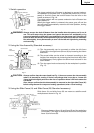
(2) Once the saw blade reaches maximum speed, push
the handle down carefully until the saw blade
approaches the workpiece.
(3) Once the saw blade contacts the workpiece, push the
handle down gradually to cut into the workpiece.
(4) After cutting the workpiece to the desired depth, turn
the power tool OFF and let the saw blade stop
completely before raising the handle from the
workpiece to return it to the full retract position.
CAUTION: * Increased pressure on the handle will not increase the cutting speed.
On the contrary, too much pressure may result in overload of the motor and/or
decreased cutting efficiency.
WARNING: * Confirm that the trigger switch is turned OFF and the power plug has been removed
from the receptacle whenever the tool is not in use.
* Always remove the lock-off button from the handle and store it in a secure place
after completing the work.
Flange Nut
Fence (B)
Slide Fence (B)
Nylon Washer
Machine Screw
Flange Nut
Fence (A)
Slide Fence (A)
Nylon Washer
Machine Screw
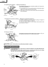
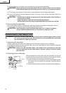
Adjusting Line
Marking
(pre-marked)
Marking
(pre-marked)
(Front View)
ab
a
b
a
b
Fig. 20