


CV-A1
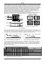
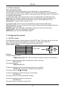
6.6. Pulse Width Control Mode
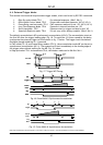
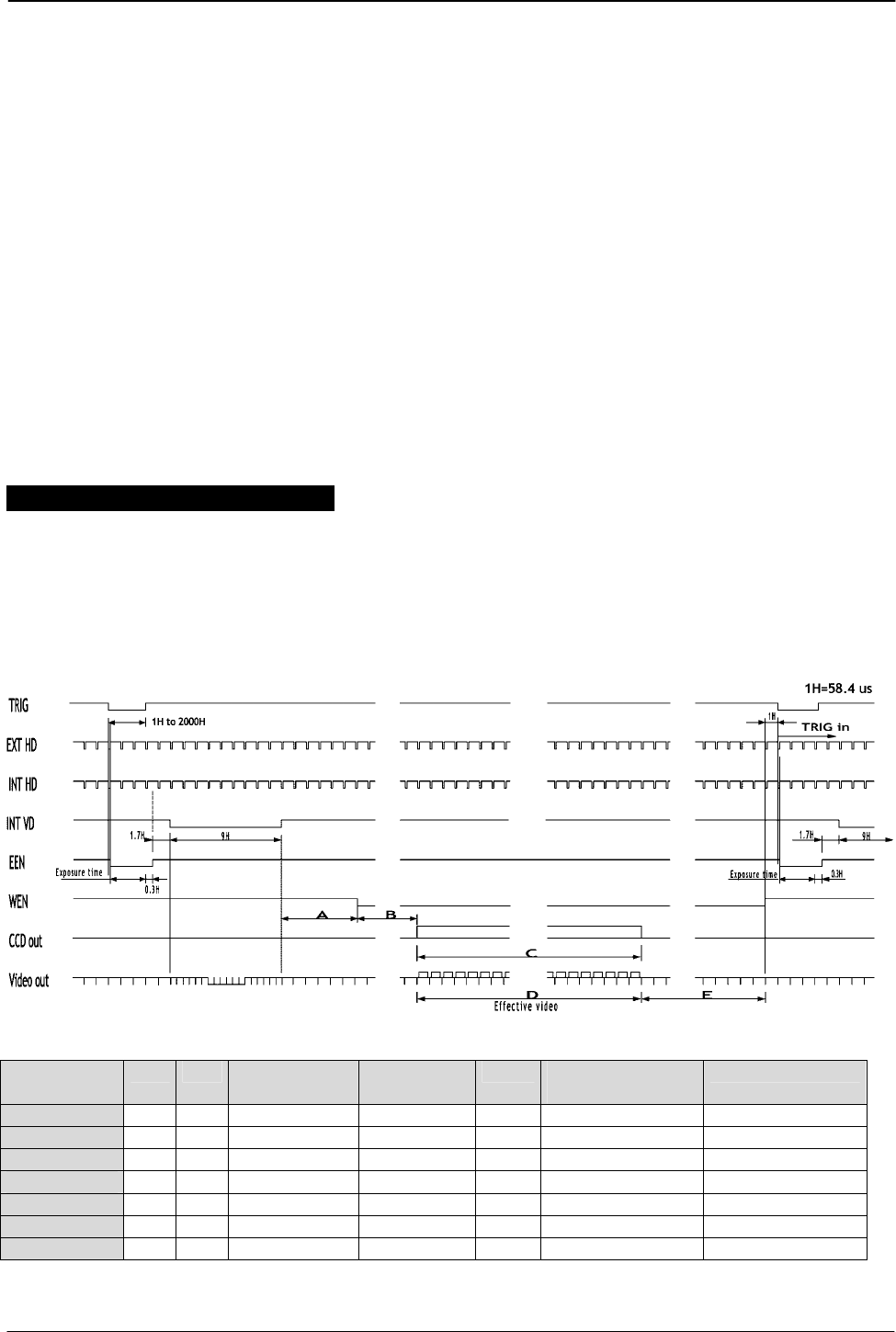
In this mode the exposure starts from the leading edge of the trigger pulse. It stops at the
trailing edge of the trigger pulse, and the resulting video is read out. The accumulation can be
either H synchronous or H asynchronous. HC=0 or HC=1. In H synchronous mode the accumulation
starts at the first HD pulse after the leading edge of the trigger. It can result in <1H jitter if the
trigger is not synchronized to H. In H asynchronous mode the accumulation starts immediately
after the leading edge of the trigger. (The internal H is not reset.)
This mode will operate with full and partial scanning and with all binning modes. Partial
scanning together with binning will work, but it is not described, and no timing diagrams are
documented. An EEN pulse will indicate the active accumulation time, and a WEN pulse
indicates that the resulting video is being read out.
To use this mode:
Set function: Trigger mode “Pulse Width Controlled” TR = 2
“H accumulation” HC=0 or HC=1
Polarity and other functions
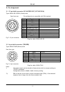
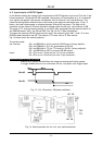
Input: Ext. trigger to pin 5 on 6 pin connector (or pin 11 on 12-pin connector).
Ext. HD to pin 6 on12-pin connector. (If used).
Important notes on using this mode.
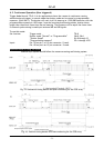
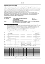
• With HC=0 the start of exposure will start synchronized to the internal H signal. The start
may be shifted max 1H. To avoid this shift (1 H jitter), synchronize the camera to an
external HD and make sure that the trigger pulse aligns to the HD as shown in fig. 17.
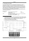
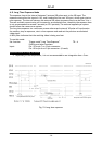
With HC=1 the exposure will start immediately. Refer to fig. 18 and fig. 19.
• The duration of the trigger can be >1H to <2000H.
• A new trigger must not be applied before WEN is high.
• In trigger modes there are no continuous VD out, only after each trigger input.
No equalize and serration pulses.
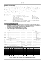
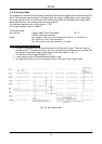
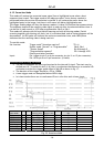
Table showing the figures for the different modes.
Scan mode
A B C
CCD array line #
D
Effective video
E Max frame rate
fps
Remarks
Full 10H 14H 4 to 1038 1035H 18H 15
1/2 Partial 17H 33H 271 to 783 513H 25H 28
1/3 Partial 17H 33H 357 to 697 341H 25H 40
1/6 Partial 17H 33H 442 to 612 171H 25H 66
H binning 10H 14H 4 to 1038 1035H 18H 15
V binning 10H 14H 18 to 1019 501H 18H 30
V+H binning 10H 14H 18 to 1019 501H 18H 30
Fig. 21. Pulse Width Control trigger mode
- 12 -
JPT 08-10-03: 11:01