


CV-A1
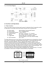
4. Locations and Functions
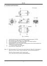
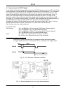
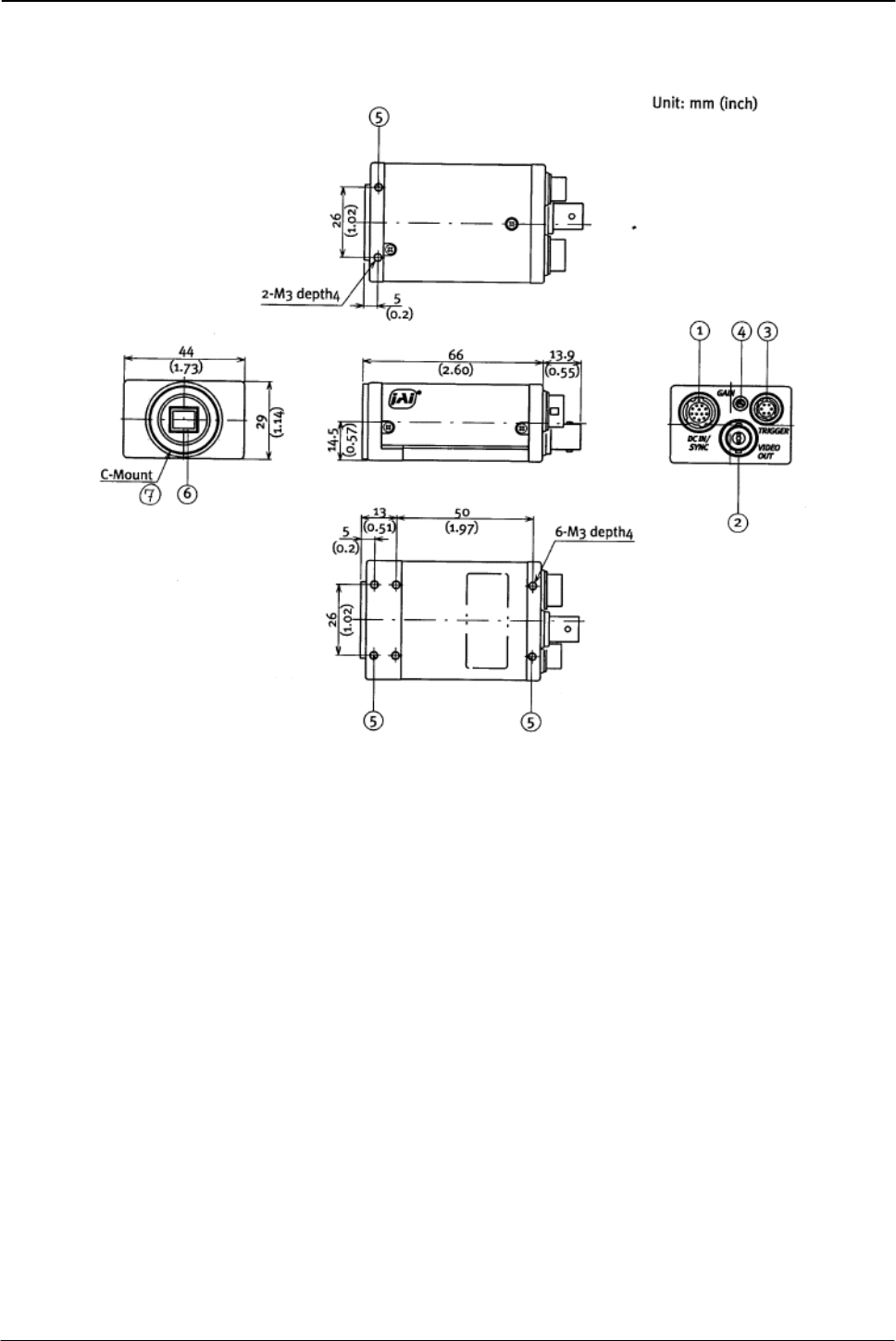
Fig. 1. Locations.
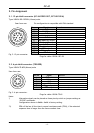
1. 12 pin Hirose connector for frame grabber interfacing and power (12V DC).
2. BNC connector for video output. VS 1.0 Vpp 75 Ohm.
3. 6 pin Hirose connector for trigger input and RS-232C control interface.
4. Gain potentiometer for manual gain setting.
5. Mounting holes, 8 x M3. For precision mounting use only the 4 holes located at the
forward part of the bottom plate.
6. 1/2” interline-transfer type CCD sensor.
7. Lens mount for C-mount lenses. *1)
Note: *1) Rear protrusion on the C-mount lens must be less than 10mm (0.4 inches approx.).
When IR-cut filter is used, it must be less than 7.0 mm (0.28 inches approx.).
The IR-cut filter is placed in the C-mount thread.
The C-mount IR-cut filter must be ordered separately.
- 3 -
JPT 08-10-03: 11:01