


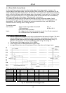
CV-A1
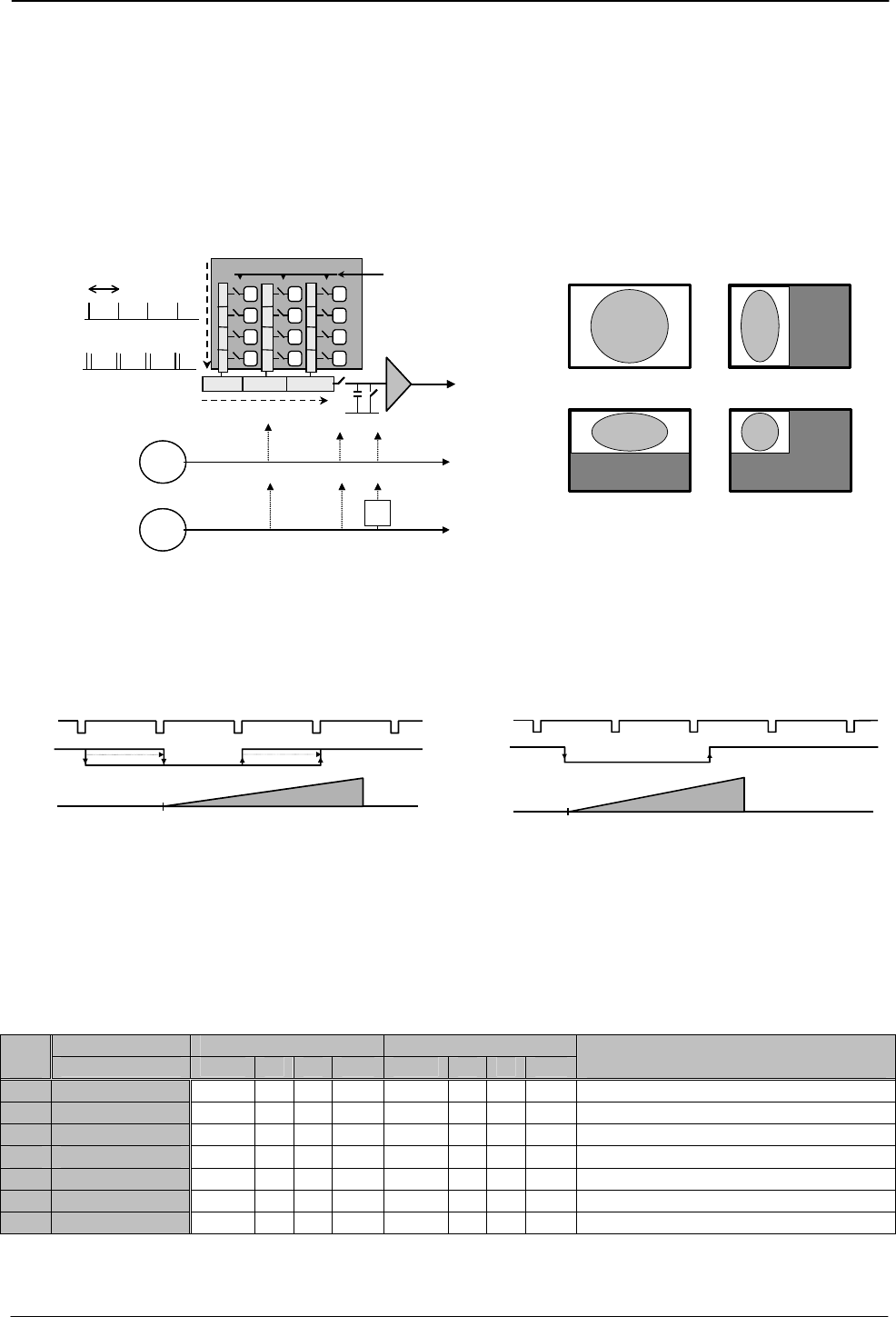
Binning mode BI is a function where the signal charge from 2 or more adjacent pixels are added
together and read out as one pixel. A resulting full frame with lower resolution can be read out
with a higher rate. By adding 2 pixels together, the sensitivity is doubled. The CV-A1 has both
vertical and horizontal binning. With V binning the pixel charge from 2 adjacent lines are added
together in the horizontal ccd register. It is done by double pulses to the vertical ccd register.
With H binning the pixel charge from 2 horizontal adjacent pixels are added together in the
sample/hold circuit after the horizontal ccd register. It is done by shifting the charge from 2
horizontal ccd cells into the sample/hold capacitor for each reset pulse.
Both vertical and horizontal binning can work together. The sensitivity is then 4 times normal.
The aspect ratio will be correct, if the sampling frequency is divided with 2. See fig. 10.
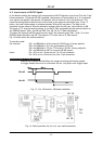
Xsg1
Video out
f pix
Pclk out
:2
Pclk out
No H binning
Horizontal ccd register
S/H Reset
S/H Reset
f pix
Pclk out
:2
Pclk out
No H binning
Horizontal ccd register
S/H Reset
S/H Reset
V and H binning.
Aspect ratio correct
Vertical binning
690 pixels
1380 pixels
501 pixels
501 pixels
V and H binning.
Aspect ratio correct
Vertical binning
690 pixels
1380 pixels
501 pixels
501 pixels
f pix
H binning
No V binning
V binning
H
V
e
r
t
i
c
a
l
c
c
d
r
e
g
i
s
t
e
r
Xsg1
Video out
f pix
H binning
No V binning
V binning
H
V
e
r
t
i
c
a
l
c
c
d
r
e
g
i
s
t
e
r
Normal full scanning.
Aspect ratio correct
Horizontal binning
Displayed image with binning
1380 pixels
690 pixels
1035 pixels
1035 pixels
H binning is 2:1. V is 2:1. Together it is a 4 :1 binning
Normal full scanning.
Aspect ratio correct
Horizontal binning
Displayed image with binning
1380 pixels
690 pixels
1035 pixels
1035 pixels
H binning is 2:1. V is 2:1. Together it is a 4 :1 binning
Fig. 10. Binning.
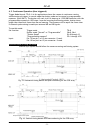
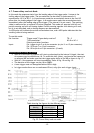
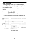
The accumulation mode HC can be set to asynchronous accumulation (HC=1). The exposure in
PWC mode (TR =2) and Frame Delay readout (TR=3) will start immediately at the leading edge of
the trigger pulse without waiting for the HD. Fig. 11 and fig. 12 shows the details.
Xb
HD
Trigger
Xb
Accum
HD
Trigger
Accum
Fig. 11. PWC H synchronous accumulation Fig 12. PWC asynchronous accumulation
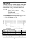
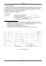
In normal trigger mode (TR=0) shutter speed up to 1/200,000 sec. can be used. In all triggered
shutter modes, the shortest shutter time is limited to ≥1,3 H. (1/12,000). In triggered shutter
modes with partial scan or binning, the longest shutter speed is not limited by the frame read
out time. It can be longer.
Trigger modes with possible scanning and binning combinations
Scanning Full scanning Partial scanning
TR=
Binning norm. V H V+H Norm V H V+H
Remarks
0 Normal
√ √ √ √ √
n n n SM=0, SM=1 active
1 Edge Pre-sel.
√ √ √ √ √
n n n SM=0, SM=1 active
2 Pulse Width
√ √ √ √ √
n n n HC=0, HC=1 active
3 Fr. Delay r.o.
√ √ √ √ √
n n n HC=0, HC=1 active
4 Long Time int
√
n n n n
5 Start/Stop
√
6 Smearless
√ √ √ √ √
n n n SM=0, SM=1 active
√ Described mode
n Non-described mode combination, which will work
- 7 -
JPT 08-10-03: 11:01