


CV-A1
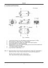
5. Pin Assignment
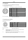
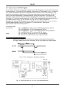
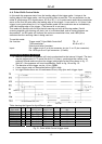
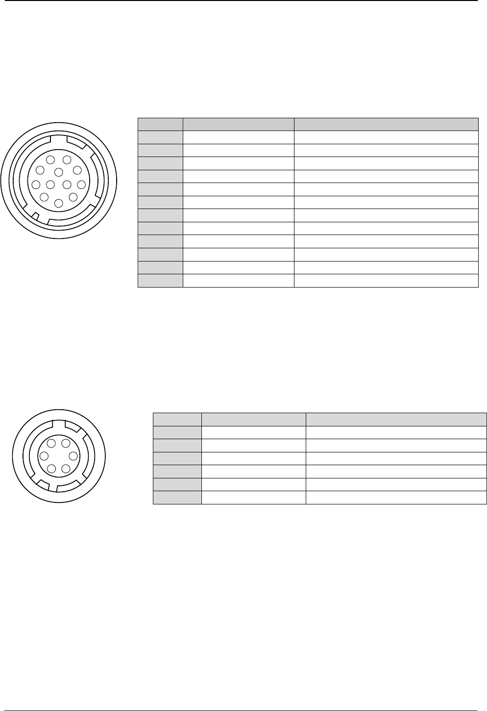
5.1. 12-pin Multi-connector (DC-IN/VIDEO OUT, EXT.HD/VD IN)
Type: HR10A-10R-12PB-01 (Hirose) male
Seen from rear Pin configuration is compatible with EIAJ standard
Fig. 2. 12-pin connector.
Plugs for cable: HR10A-10P-12S
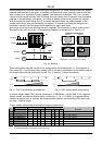
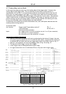
5.2. 6-pin Multi-connector (TRIGGER)
Type: HR10A-7R-6PB (Hirose) male
Pin no. Signal Remarks
1 GND
2 +12 V DC input
3 GND
4 Video output
Parallel with the BNC connector.
5 GND
6 HD input/HD output
*) SW2.1 on for 75Ω. SW1.1 on for HD out.
7 VD input/VD output
*) SW2.2 on for75Ω. SW1.2 on for VD out.
8 GND
9 Pixel clock output
*) JP2 short and PC=1 for pclk out.
10 WEN output
*) GND if JP5 open and JP3 short
11 Trigger input
*) +12V DC if JP1 short and JP4 open
12 GND
Pin no. Signal Remarks
1 TXD out
2 RXD in
3 GND
4 GND
5 Trigger input
*) Parallel with pin 11 on 12 pin con
6 EEN output
*) *2). WEN output if EW=1
3
4
5
6
7
8
9
10
11
12
1
2
Seen from rear.
1
2
3
4
5
6
Fig. 3. 6-pin connector.
Plugs for cable: HR10A-7P-6S
Notes.
*) Alternative signals can be placed on these pins by switch or jumper settings or
RS-232C commands.
Configurations shown in Bold + italic is factory setting.
*2) EEN will be low all the time in normal continous mode (TR=0), if the selected
exposure time is longer than the frame readout time.
- 4 -
JPT 08-10-03: 11:01