


CV-A33CL
5.3. Input and Output Circuits
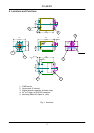
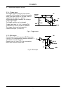
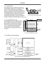
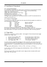
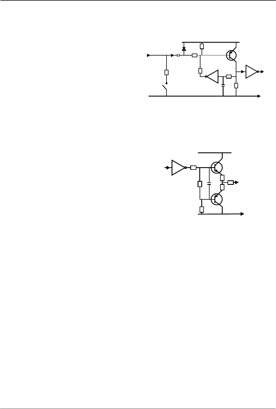
5.3.1. Trigger input
The trigger inputs on pin #10 12 pin Hirose
connector is AC coupled. To allow a long pulse
width, the input circuit is a flip flop, which is
toggled by the negative or positive
differentiated spikes caused by the falling or
rising trigger edges.
GND
+5V
15k
TTL
1k
GND
100n
1k
68k
100k
1n
Trig input
pin #10
75Ω
SW 300
GND
+5V
15k
TTL
1k
GND
100n
1k
68k
100k
1n
Trig input
pin #10
75Ω
SW 300
The trigger polarity can be changed.
Trigger input level 4 V ±2 V. It can be 75Ω
terminated by internal SW300 on PK8388A.
The trigger inputs can be changed to
Camera Link input. (TI=0 for CL)
Fig. 4. Trigger input.
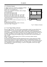
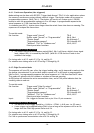
5.3.2. EEN output
GND
+5V
2
2
10k
2k2
75
TTL
100
#9/12
EEN output
GND
+5V
2
2
10k
2k2
75
TTL
100
#9/12
EEN output
On pin #9 on 12 pin HR connector EEN The output
circuit is 75 Ω complementary emitter followers. It
will deliver a full 5 volt signal.
Output level ≥4 V from 75Ω. (No termination).
EEN is also found in Camera Link.
Fig. 5. EEN output
- 5 -