


CV-A33CL
- 7 -
6. Functions and Operations
In the following the format shown in “7.3. CV-A33CL command list” are used for function
commands and parameters.
6.1. Basic functions
The CV-A33CL camera is a progressive scan camera with 10 or 8 bit video output in single
channel Camera Link.
Programmable partial scan, where the start line and the number of lines can be selected with 1
line increment is also available.
There are 4 modes: Normal continuous, and 3 trigger modes: Edge Pre-Select (EPS), Pulse Width
Control (PWC) and Auto Trigger.
The accumulation is LVAL a-synchronous.
In the following some of the functions are shown in details.
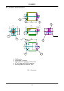
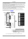
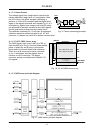
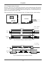
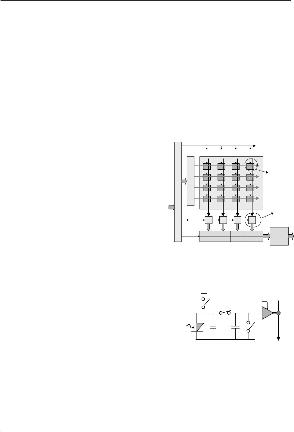
6.1.1. CMOS Sensor
The CMOS sensor principle layout is shown.
T
I
M
I
N
G
R
O
W
D
E
C
O
D
E
2 x 10 bit digital shift register
Video
process
Pixel
Column
Process
and A/D
Control
and
set up
T
I
M
I
N
G
R
O
W
D
E
C
O
D
E
2 x 10 bit digital shift register
Video
process
Pixel
Column
Process
and A/D
Control
and
set up
The sensor is an array of active photosensitive
pixels. The global shutter is working
simultaneously on all pixels. The readout can be
random row by row. 4 columns are feed through
a 4 to 1 multiplexer to an A/D converter. The
digitized row signals are placed in a vertical
register by a 1 to 4 multiplexing. From here it is
read out with the pixel clock pulses, even if the
window of interest has fewer columns. The
frame speed depends only of the height of the
window, not of the width.
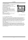
Pixel principle and column processing with A/D
converting is shown below.
Fig. 7. CMOS principle layout
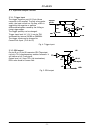
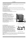
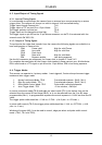
6.1.2. Pixel principle
Each pixel consists of a sensing part, a pixel memory
and an amplifier. The function can in short be
described. The photo diode and charge capacitor is
reset when switch 1 is closed. The signal accumulation
starts when sw 1 open. The charge is transferred to the
pixel memory capacitor when sw 2 close. The
accumulation stop when sw 2 open, and the signal is
now temporary stored in the memory capacitor. After
reset of the charge capacitor, a new accumulation can
start. The signal on the pixel memory capacitor is read
out to the column by the read row signal. The memory
can now be reset.
Start exposure Stop exposure
Reset
memory
Light
Photo
diode
Pixel
memory
Read row
To column
processing
Buffer
amplifier
12
3
4
Charge
capacitor
Start exposure Stop exposure
Reset
memory
Light
Photo
diode
Pixel
memory
Read row
To column
processing
Buffer
amplifier
12
3
4
Charge
capacitor
Fig. 8. Pixel principle.
With this construction all pixels will integrate at the same time, (Global shutter). The resulting
image is temporary stored in the pixel memory during read out, while a new exposure can be
started.
All timing is set up in the timing block by an internal serial link.