


1-10
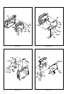
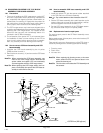
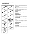
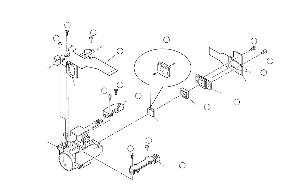
Fig. 1-6-1
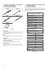
1.6 DISASSEMBLY/ASSEMBLY OF 0 OP BLOCK
ASSEMBLY/CCD BOARD ASSEMBLY
1.6.1 Precautions
1. Take care in handling the CCD image sensor, optical LPF
and lens components when performing maintenance
etc., especially with regard to surface contamination, at-
tached dust or scratching. If fingerprints are present on
the surface they should be wiped away using either a
silicon paper, clean chamois or the cleaning cloth.
2. The CCD image sensor may have been shipped with a
protective sheet attached to the transmitting glass. When
replacing the CCD image sensor, do not peel off this
sheet from the new part until immediately before it is
mounted in the OP Block Assembly.
3. The orientation of the optical LPF is an important factor
for installation. If there is some marking on the LPF, be
sure to note it down before removing and to reassem-
ble it very carefully as it was referring to the marking.
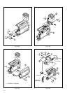
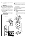
1.6.2 How to remove CCD board assembly and CCD
base assembly
1. Unsolder the CCD board assembly by the 14 points
(SD0) and then remove it.
2. Remove the two screws (1, 2) and remove the CCD base
assembly.
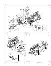
Note
0
a:
When removing the CCD base assembly, pay
heed to the CCD image sensor because the
spacer rubber and optical LPF are occasionally
removed together with the CCD image sensor.
Note
0
b:
When replacing the CCD image sensor, don’t re-
place it individually but replace the CCD base as-
sembly in whole with a new one.
1.6.3 How to assemble CCD base assembly and CCD
board assembly
1. Install the optical LPF with the spacer rubber attached
to its CCD side in the OP block assembly.
Note
0
c:
Pay careful attention to the orientation of the LPF.
2. Set the CCD base assembly with careful attention to the
spacer rubber not to come off the right position, and fas-
ten them together with the two screws (1, 2).
3. Set the CCD board assembly in the CCD base assem-
bly, and then solder it by the 14 points (SD0).
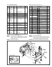
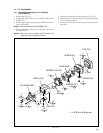
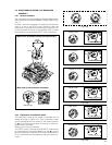
1.6.4 Replacement of service repair parts
The service repair parts for the OP Block Assembly are as
listed below.
Before replacement of these parts, remove the bracket (OP
assembly) as required.
Take special care not to disconnect any of the FPC wires or
cause any damage due to soldering (excessive heating).
1. Focusing motor
2. Zoom motor
3. Iris motor unit
Note
0
d:
When replacing the focusing motor or the zoom
motor, solder the FPC at a space of about 1 mm
above the terminal pin.
Note
0
e:
The iris motor unit includes the FPC Assembly and
two sensors.
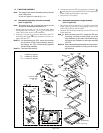
CCD BOARD ASSY
(SD )
CCD BASE ASSY
OPTICAL LPF
ZOOM MOTOR
SPACER RUBBER
∗
9
(S c)
10
∗
8
(S c)
10
∗
7
(S b)
10
∗
1
(S a)
10
∗
6
(S b)
10
∗
3
(S b)
10
∗
4
(S b)
10
∗
5
(S b)
10
∗
2
(S a)
10
BKT(OP) ASSY
SENSOR
SENSOR
Note d
10
Note a
10
OPTICAL LPF
IRIS
MOTOR
UNIT
Note c
10
Note b
10
Note e
10
FOCUS
MOTOR
Note d
10
OP
side
CCD
side
Blue
10
∗
: 0.078 N
•
m (0.8 kgf
•
cm)