


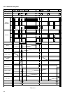
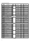
2-8
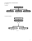
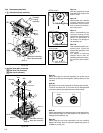
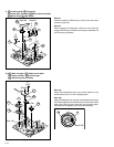
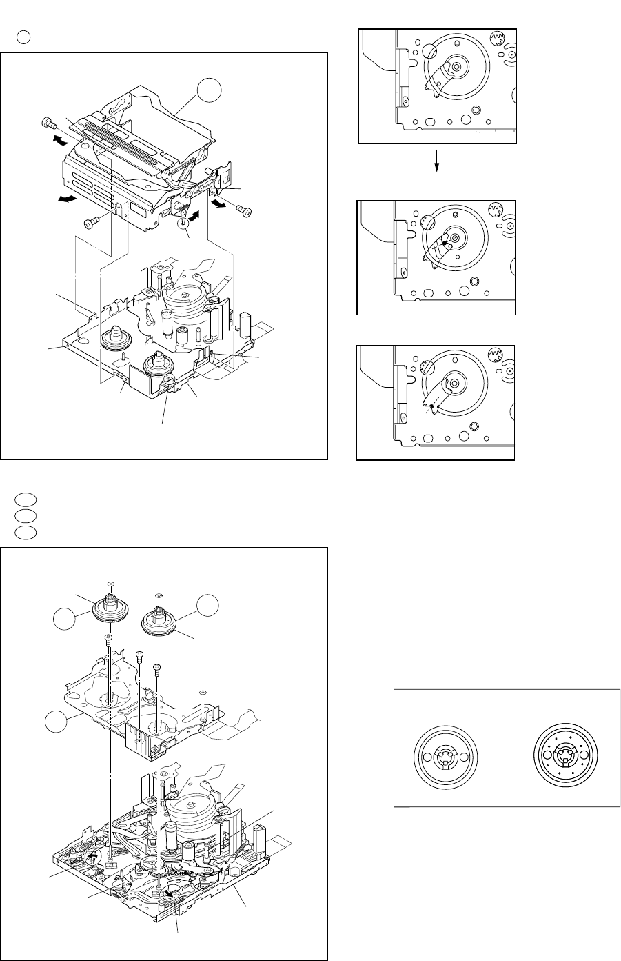
Fig. 2-4-5
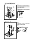
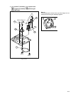
Fig. 2-4-6
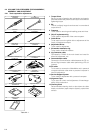
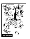
2.4.2 Disassembly/assembly
1. A Cassette housing assembly
2. 2a Reel disk (SUP) assembly
2b Reel disk (TU) assembly
2c Reel cover assembly
2
(S1)
3
(S1)
Cassette
housing
assembly
1
(S1)
Slide deck assembly
/Main deck assembly
(L1b)
(L1a)
(L1a)
(L1c)
Note 1c
(L1d)
(L1b)
A
Note 1b
2c
(W2)
(W2)
(W2)
6
(S2b)
4
(S2a)
5
(S2a)
2a
2b
Slide deck assembly
/Main deck assembly
Note 2a
Note 2c
Note 2a
Note 2c
Note 2b
Note 2b
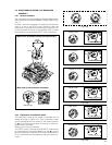
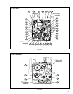
Note 1a:
Shift the mechanism mode
from the STOP mode to the
EJECT mode.
Note 1b:
Reassemble the cassette
housing assembly to the
mechanism as the cancel
lever is moved in the direc-
tion of the arrow.
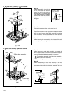
Note 1c:
When reassembling the
cassette housing to the
mechanism, make sure that
there is no deformation in
the frame or no damage to
the switches, etc.
Note 1d:
After reassembling the com-
ponent parts, check the
mechanism operation in the
PLAY mode.
For details of checking
method, refer to “2.6.1 as-
sembling slide deck assem-
bly and main deck assem-
bly”.
<STOP mode>
<EJECT mode>
<PLAY mode>
Note 2a:
When removing the reel disk assembly, be careful not to
break the brake pad which applies lateral pressure to the
reel disk.
Note 2b:
Be careful not to make a mistake in installing the reel disk.
The SUP reel disk and TU reel disk can be distinguished
from each other by the appearance as shown below.
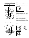
Note 2c:
When reassembling the cassette housing to the mechanism,
make sure that there is no deformation in the frame or no
damage to the switches, etc.
Note 2d:
When fitting the reel cover assembly to the set, carefully
tighten the screw with the specified tightening torque of
0.069N
•
m (0.7kgf
•
cm).
(SUP) (TU)