


2-1
SECTION 2
MECHANISM ADJUSTMENT
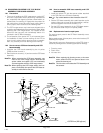
2.1 PRELIMINARY REMARKS ON ADJUSTMENT AND
REPAIR
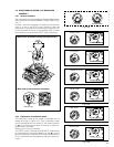
2.1.1 Precautions
1. When fastening parts, pay careful attention to the tight-
ening torque of each screw. Unless otherwise specified,
tighten a screw with the torque of 0.039 N
•
m (0.4 kgf
•
cm).
2. Be sure to disconnect the set from the power supply be-
fore fastening and soldering parts.
3. When disconnecting/connecting wires, be careful not to
get them and their connectors damaged. (Refer to the
Section 1.)
4. When replacing parts, be very careful neither to dam-
age other parts nor to fit wrong parts by mistake.
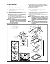
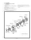
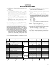
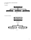
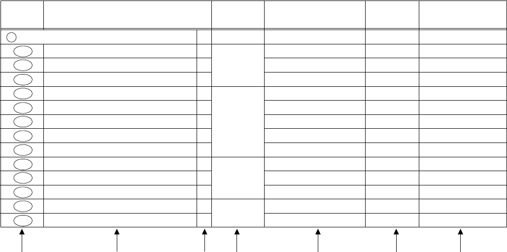
2.1.2 Notes on procedure for disassemby/assembly
The disassembling procedure table (Table 2-4-1 on page
2-6, a part of the table is shown below for reference)shows
the procedure to disassemble/reassemble mechanism
parts.
Carefully read the following explanation before starting ac-
tual disassembling/reassembling work. The item numbers
(circled numbers)in the following explanation correspond
to those appearing under respective columns of the table.
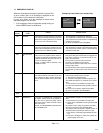
(1) Circled numbers appearing in this column indicate the
order to remove parts. When reassembling, follow these
numbers in the reverse order. Circled numbers in this
column correspond to those appearing in drawings of
this section.
(2) This column shows part names corresponding to circled
numbers in the left column.
(3) The symbol (T or B)appearing in this column shows the
side which the objective part is mounted on.
T =the upper side, B =the lower side
(4) Symbols appearing in this column indicate drawing
numbers.
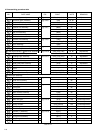
Step Part Name Fig. Point Note Remarks
(5) This column indicates parts and points such as screws,
washers, springs, and others to be removed/fitted for
disassembling/reassembling the mechanism. Besides
such the parts, this column occasionally indicates work-
ing points.
P = Spring
W = Washer
S = Screw
∗ = Lock (L),soldering (SD),shield,connector (CN),
etc.
Example • Remove (W1)=Washer W1.
• ∗Remove the solder at (SD1)=Point SD1.
• ∗Disconnect
Å
=Connector
Å
.
(6) Numbers in this column represent the numbers of notes
in the text. For example, “1” means “Note 1”.
(For parts that need phase adjustment after reassem-
bling, refer to “2.6 MECHANISM ADJUSTMENTS”.)
(7) This column indicates required after disassembling/re-
assembling work such as phase adjustment or mecha-
nism adjustment.
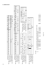
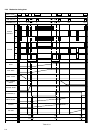
(1) (2) (3) (4) (5) (6) (7)
NO. PART NAME FIG. POINT NOTE REMARKS
A Cassette housing assembly T Fig. 2-4-5 3(S1),(L1a)-(L1d)
1a, 1b, 1c, 1d
Adjustment
2a Reel disk (SUP) assembly T Fig. 2-4-6 (W2) 2a, 2b
2b Reel disk (TU) assembly T Fig. 2-4-6 (W2) 2a, 2b
2c Reel cover assembly T Fig. 2-4-6 (S2b),2(S2a),(W2) 2d
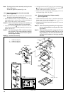
3a Tension arm assembly T Fig. 2-4-7 (W3a) 3b
3b Release guide assembly T Fig. 2-4-7 - 3a
3c Idler arm assembly T Fig. 2-4-7 (W3b) -
3d Guide arm assembly T Fig. 2-4-7 - 3a
3e Pinch roller arm assembly T Fig. 2-4-7 (W3a) -
4a Cleaner arm assembly T Fig. 2-4-8 (L4a) 4a
4b Slant pole arm assembly T Fig. 2-4-8 (W4),(L4b),(P4a),(P4b) 4b
4c Drum assembly T Fig. 2-4-8 3(S4) -
5a Guide roller (S) assembly T Fig. 2-4-9 (P5) 5a
5b Rail assembly T Fig. 2-4-9 3(W5a), (W5b) 5b, 5c