


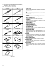
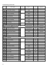

2-10
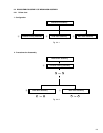
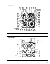
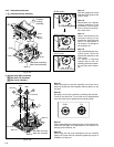
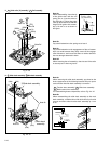
Fig. 2-4-9
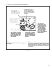
Note 5a:
When reassembling, insert the tip
of the guide roller with the coil
spring put on it into the hole on
the main deck. Tighten the guide
roller by about 6 turns so that the
height of the guide roller assem-
bly is 19 mm or so as shown in
the figure.
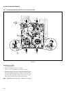
5. 5a
G
uide roller (S) assembly/
5b
Rail assembly
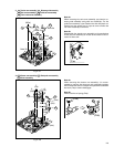
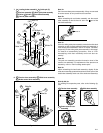
Fig. 2-4-10
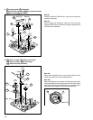
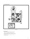
6. B
Slide deck assembly/
C
Main deck assembly
Note 5b:
Pay careful attention to the spring not to lose it.
Note 5c:
Pay careful attention to the engagement of the rail assem-
bly’s arm ends because they easily come off the engage-
ment. Moreover, make sure that there is neither deforma-
tion nor damage observed in them.
Note 5d:
When removing the rail assembly, check to see if the collar
is securely set in the arm groove.
Note 6a:
When removing the slide deck assembly, pay heed to the
three components of the following because they are apt to
come off after the slide deck assembly is removed.
8a
Tension lever assembly/
8b
Slide lever assembly
8c
Brake control lever assembly
For reassembling those components, refer to Fig. 2-4-12.
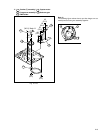
Note 6b:
When reassembling the slide deck assembly to the main
deck assembly, combine them with each other by the side
grooves and then slide the slide deck assembly by 1 mm
or so.
Guide roller
(s) assembly
19mm
1mm
5b
(W5a)
(W5a)
(W5a)
(W5b)
(P5)
Note 5b
Note 5c
Note 5a
Note 5d
5a
CMain deck
assembly
BSlide deck assembly
(L6a)
(L6b)
(L6d)
(L6c)
Note 6b
Note 6a
(W6)