


EN 77
Master Page: Right
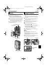
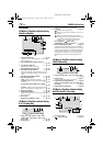
Controls
a •E-Mail Clip Recording Button
[E-MAIL]............................................ ੬ pg. 49
•Information Button [INFO]................ ੬ pg. 26
b Menu Button [MENU].......................... ੬ pg. 31
c •+, – Button ........................................ ੬ pg. 31
•LCD Monitor Brightness Control
[MONITOR BRIGHT +, –]................. ੬ pg. 13
d •Power Zoom Ring [T/W].................... ੬ pg. 18
•Shuttle Search Ring
[SHUTTLE SEARCH, 3/5]........ ੬ pg. 20
e •Recording Start/Stop Button.............. ੬ pg. 17
•Play/Pause Button [4/9].................. ੬ pg. 20
f Power Switch [A, M, P, OFF].......... ੬ pg. 13
g Lock Button ......................................... ੬ pg. 13
h Snapshot Button [SNAPSHOT]....... ੬ pg. 23, 41
i •Stop Button [8].................................੬ pg. 20
•Digital Sound Button [D.SOUND]..... ੬ pg. 46
j •Index Button [INDEX] ........... ੬ pg. 26, 46, 56
•Navigation Button [NAVI] .................੬ pg. 47
k Set/Select Button [SET/SELECT]........... ੬ pg. 31
l Battery Release Switch
[BATT.RELEASE]...................................੬ pg. 11
m Cassette Open/Eject Switch
[OPEN/EJECT]......................................੬ pg. 15
n Thumbnail Storing Button
[NAVI STORE]...................................... ੬ pg. 47
o VIDEO/MEMORY Switch
[VIDEO/MEMORY].............................. ੬ pg. 13
p •Focus Adjustment Button [FOCUS] ... ੬ pg. 43
•Speaker Volume Control [VOL. +]..... ੬ pg. 20
q •Backlight Compensation Button
[BACK LIGHT]................................... ੬ pg. 45
•Speaker Volume Control
[VOL. –] ............................................ ੬ pg. 20
r Dioptre Adjustment Control................ ੬ pg. 12
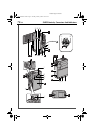
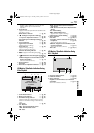
Connectors
The connectors are located beneath the covers.
S Digital Video Connector [DV IN/OUT]
(i.Link*)....................................੬ pg. 51, 52, 62
* i.Link refers to the IEEE1394-1995 industry
specification and extensions thereof. The logo
is used for products compliant with the i.Link
standard.
T USB (Universal Serial Bus)
Connector............................................੬ pg. 62
U S/AV connector ....................... ੬ pg. 22, 50, 59
V Headphone Connector [ ] ................ ੬ pg. 56
No sound is output from the speaker when
headphones are connected to this connector.
Indicators
A Power Lamp....................................੬ pg. 13, 17
B Tally Lamp......................................੬ pg. 17, 37
Other Parts
Y LCD Monitor..................................੬ pg. 12, 18
a Battery Pack Mount..............................੬ pg. 11
b Speaker ................................................੬ pg. 20
c Grip Belt/Strap Eyelet.............................੬ pg. 6
d Viewfinder............................................੬ pg. 12
e Viewfinder Cleaning Hatch ..................੬ pg. 73
f Cassette Holder Cover..........................੬ pg. 15
g Camera Sensor
Be careful not to cover this area, a sensor
necessary for shooting is built-in here.
h Stereo Microphone...............................੬ pg. 56
i Info-Shoe
Attach only the optional JVC VL-V3U Video
Light, VL-F3U Flash, MZ-V3U Stereo Zoom
Microphone or MZ-V5U Stereo Microphone.
Make sure to turn off the power of the camcorder
and the video light, flash or microphone before
attaching and removing them.
j Lens
k Lens Cover............................................੬ pg. 17
l Grip Belt Eyelet......................................੬ pg. 6
m Remote Sensor .....................................੬ pg. 54
n Tripod Mounting Socket.......................੬ pg. 12
o Card Cover [MEMORY CARD] ............੬ pg. 16
REFERENCES
GR-DVP10PAL.book Page 77 Tuesday, January 6, 2004 10:55 AM