


EN87
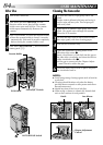
Controls
1 E-MAIL CLIP REC Button ......................੬ pg. 61
2 MENU Button ......................................੬ pg. 40
3 •+, – Button ........................................੬ pg. 40
•LCD Monitor Brightness Control
[MONITOR BRIGHT +, –] .................੬ pg. 20
4 •Power Zoom Ring [T/W] ...................੬ pg. 21
•SHUTTLE SEARCH Ring
[2/3].......................................੬ pg. 23
5 •Recording Start/Stop Button...............੬ pg. 20
•Play/Pause Button [4/6] ..................੬ pg. 23
6 Power Switch
[ , , , OFF] ............................੬ pg. 18
7 Lock Button .........................................੬ pg. 18
8 •Snapshot Button
[SNAPSHOT] ............੬ pg. 28, 29, 52, 60, 61
9 •D.SOUND Button .............................੬ pg. 56
•Stop Button [5] .................................੬ pg. 23
0 INDEX Button ................................੬ pg. 32, 56
! SET/SELECT Button...............................੬ pg. 40
@ Battery Release Switch
[BATT. RELEASE] .................................. ੬ pg. 11
# OPEN/EJECT Switch .............................੬ pg. 14
$ •FOCUS Button ..................................੬ pg. 53
•BLANK Button...................................੬ pg. 26
% VIDEO/MEMORY Switch
[VIDEO, MEMORY] .............................੬ pg. 18
^ •EXPOSURE Button.............................੬ pg. 54
•Speaker Volume Control
[VOL. +]............................................੬ pg. 23
& •BACKLIGHT Button...........................੬ pg. 54
•Speaker Volume Control
[VOL. –] ............................................੬ pg. 23
* Diopter Adjustment Control .................੬ pg. 12
( Lock Button .........................................੬ pg. 20
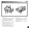
Connectors
The connector is located beneath a cover.
Audio/Video Output Connector
[AV OUT] ................................੬ pg. 24, 58, 70
Digital Video Connector
[DV IN/OUT] (i.link*) ..............੬ pg. 59, 74, 75
* i.Link refers to the IEEE1394-1995 industry
specification and extensions thereof. The logo
is used for products compliant with the i.Link
standard.
Multi Connector
When attached to the Docking Station, this part
is connected.
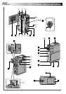
Indicators
Power Lamp...................................੬ pg. 18, 20
Tally Lamp .....................................੬ pg. 20, 42
Other Parts
LCD Monitor..................................੬ pg. 20, 21
Battery Pack Mount..............................੬ pg. 11
Speaker................................................੬ pg. 23
Grip Belt/Strap Eyelet .............................੬ pg. 7
Viewfinder ...........................................੬ pg. 12
Viewfinder Cleaning Hatch ..................੬ pg. 84
Cassette Holder Cover .........................੬ pg. 14
Stereo Microphone ..............................੬ pg. 66
Info-Shoe
Attach the optional video light/flash/zoom
microphone. Make sure to turn off the power of
the camcorder and the video light/flash/zoom
microphone before attaching and removing them.
Camera Sensor
Be careful not to cover this area, a sensor
necessary for shooting is built-in here.
Lens
It is not possible to attach any lens filter or
conversion lens.
Lens Cover...........................................੬ pg. 20
Grip Belt Eyelet......................................੬ pg. 7
Remote Sensor .....................................੬ pg. 62
Tripod Mounting Socket .......................੬ pg. 12
MEMORY CARD Cover........................੬ pg. 16