


E12
@@@@@@
1. Introduction (continued)
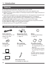
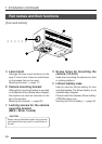
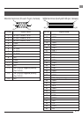
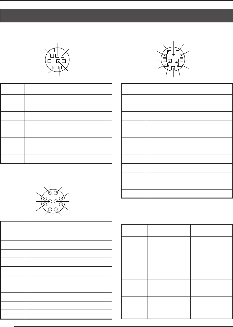
Power terminal (Mini DIN 8-pin, female)
Explanation of terminals
1
4
3
6
7
8
5
2
Pin no. Signal name
1NC
2 GND
3NC
4NC
5 GND
6 12V
7NC
8 12V
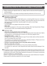
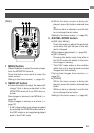
Remoter terminal (Metal 10-pin, female)
Pin no. Signal name
1 A. WHITE active Zi=22k Ω
2 FREEZE L active Zi=100k Ω
3
WEN L active Zo=100 Ω 3V(p-p)
4 FLASH
5 SEND (PRINT)
6 RS-SDI
7 RS-SDO
8 GND
9 12V
10 OPERATION
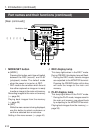
Lens terminal (Metal 12-pin, female)
1
2
8
7
10
6
3
4
5
9
Pin no. Signal name
1NC
2
3 GND
4NC
5 IRIS CONTROL
6 12V DC
7 IRIS POSITION
8 IRIS AUTO /MANU
9NC
10 NC
11 NC
12 NC
6
7
8
2
1
9
3
4
12
5
10
11
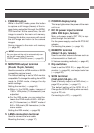
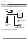
Terminal
name
FREEZE
WEN
FLASH
Conditions
• Contact point
recommended
• Rated voltage:
5.3V
• H level: 3.5 ~ 5.0V
• L level: 0 ~ 0.8V
• CMOS (5V): OK
• TLL not possible
• Output only when
in the SXGA mode
• Rated current:
150mA
• Rated voltage:
12V
I/O
IN
• 5V CMOS
• Schmidt Trigger
• Pull-up to 5V at
100k Ω
• Input capacity
0.1 µF
OUT
• 3.3V (p-p)
negative polarity
OUT
• Open collector