


6
Installation (continued)
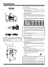
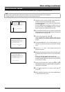
4.
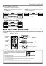
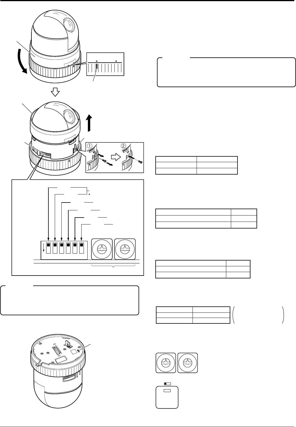
Turn the camera body cover to anti clockwise to set the word
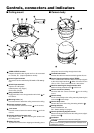
“RELEASE” on the camera body cover over the mark, then pull
the camera body cover upward.
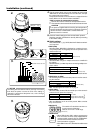
Transportation bracket is mounted when it is shipped from the
factory. Make sure to remove it before installation.
<How to remove the transportation bracket>
1
Remove the screw to remove the transportation bracket.
2
Then fasten the dome cover with the screw which was removed.
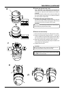
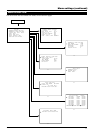
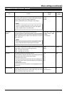
MANUAL SW3
Displayed OFF
Not displayed ON
(Initial set: OFF)
SW4PROTOCOL (1)
Point to point OFF
Multi drop (when using the RM-P2580)
ON
(Initial set: OFF)
PROTOCOL (2)
SW5
Duplex (when using the RM-P2580)
OFF
Simplex ON
(Initial set: OFF)
SYNC SW6
INT OFF
LL ON
(Initial set: OFF)
LL mode
U type: 60 Hz area only
E type: 50 Hz area only
LOCK
RELEASE
LOCK
RELEASE
LOCK
RELEASE
Camera body
cover
Camera body
cover
Mark
Setting
switches
Board
4.
ON
123456
0
9
8
7
6
5
4
3
2
1
0
9
8
7
6
5
4
3
2
1
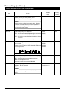
SW1
Reserved
This switch must be set OFF.
DOUBLE
FIGURES
SINGLE
FIGURES
DISP
Machine ID
SW2
SW3
SW4
SW5
SW6
PROTOCOL (1)
PROTOCOL (2)
SYNC
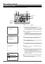
5.
Transportation bracket
TERM switch
5.
0
9
8
7
6
5
4
3
2
1
0
9
8
7
6
5
4
3
2
1
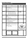
(Initial set: 00)
ON OFF
RX TERM
(110 Ω)
SC46125-002
(Initial set: ON)
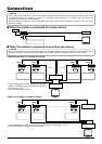
Ref. “Control signal connection” is on page 9.
●TERM switch
• When SW4 is set to ON in order to connect more
than one camera in series, set the TERM switch of
only the terminal camera to ON. The TERM switch-
es of the other cameras should be set to OFF.
See “Connections” on page 8.
• When SW4 is set to OFF, this switch should be set to
ON.
●Machine ID
The machine ID should be set when us-
ing the camera in Multi drop.
Choose an ID in the 1 to 32 range.
●SYNC (SW6)
When this switch is set to ON, the vertical sync of the camera is
locked to the AC power line frequency.
• SW1 and SW2 are not in use for the present. Make sure that
they are set to OFF.
●PROTOCOL (2) (SW5)
Set according to the communication protocol used for control-
ling the cameras.
When set to Multi drop, be sure to set the Machine ID of each camera.
●PROTOCOL (1) (SW4)
Selects whether a single or multiple cameras are controlled in
the system.
Set PROTOCOL(1) to Multi drop when connecting multiple cam-
eras in series.
If the power is supplied without removing the transportation
bracket, initialization won’t be carried out properly, so that the
camera cannot be controlled with a remote control unit.
Make sure that it is removed.
CAUTION
5.
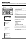
Check the switch settings and the communication protocol.
Read the controller specifications carefully before proceeding
to the switch settings.
■ Switch settings
DISP, PROTOCOL (1), (2), SYNC, Machine ID. Set these switch-
es as required.
●DISP (SW3)
Selects whether “MANUAL” is displayed or not when the cam-
era's preset position is changed by the manual operation of the
remote control unit.
The setting of these switches will be read only once at the
time when the power is turned on. Even if the setting is
changed in a state where the power is on, such a change
will not be reflected.
CAUTION