


8
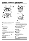
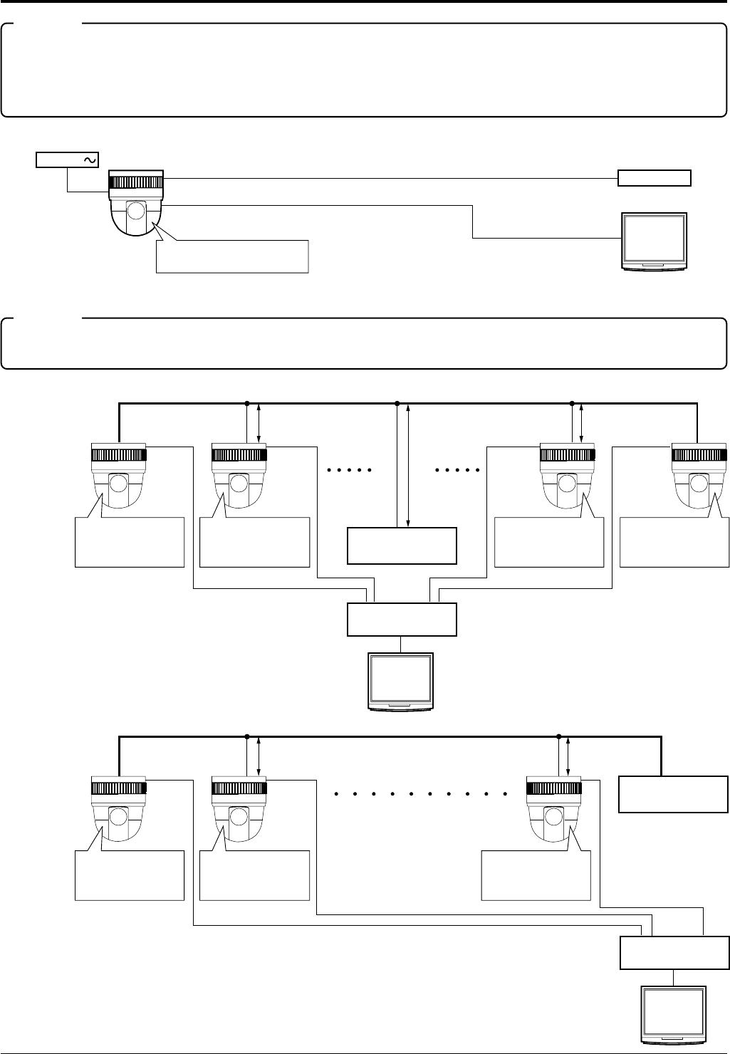
Connections
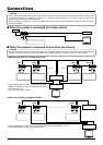
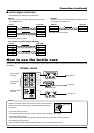
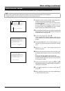
■ When the system is composed of a single camera
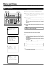
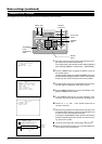
■ When the system is composed of more than one camera
Controller*
Monitor
VIDEO OUT
CONTROL
PROTOCOL(1) SW4 :OFF
TERM : ON
24V AC
VIDEO
SWITCHER, etc.
CONTROLLER*
length of stub
length of stub
CONTROL Cable
CAM1 CAM2 CAM31 CAM32
PROTOCOL(1) : ON
MACHINE ID : 01
TERM : ON
PROTOCOL(1) : ON
MACHINE ID : 02
TERM : OFF
PROTOCOL(1) : ON
MACHINE ID : 31
TERM : OFF
PROTOCOL(1) : ON
MACHINE ID : 32
TERM : ON
length of stub
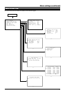
VIDEO
SWITCHER, etc.
CONTROLLER*
length of stub
CONTROL Cable
PROTOCOL(1) : ON
MACHINE ID : 01
TERM : ON
PROTOCOL(1) : ON
MACHINE ID : 02
TERM : OFF
PROTOCOL(1) : ON
MACHINE ID : 32
TERM : OFF
length of stub
CAM1 CAM2 CAM32
Terminate it
with 110ohm.
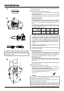
If this camera and the cables connected to this camera is used where there are strong electromagnetic waves or where there
is magnetism present, for example near a radio or TV transmitter, power transformer or an electric motor, the picture may
produce noise and the colors may be affected.
Optional controller is required to use the TK-C675B camera. Please contact your local dealer or installer for more information
about this controller.
CAUTION
Be sure to terminate the control signal cable at both ends. The cables (length of stub) connecting to non-terminated equipment
(camera or controller) must be as short as possible. If the length of stub is long, control may not be made correctly.
CAUTION
• Set the TERM switches of the cameras at both ends
(CAM1 and CAM32) to ON, and TERM switches of the
other cameras to OFF.
• Do not terminate at the controller.
• Set the TERM switch of CAM1 to ON, and also, terminate at the controller with 110 ohm.
Set the TERM switches of the other cameras to OFF.
● When the controller is located at the end.
● When the controller is not located at the end.