


7
6.
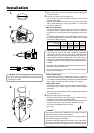
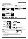
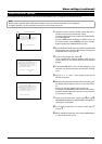
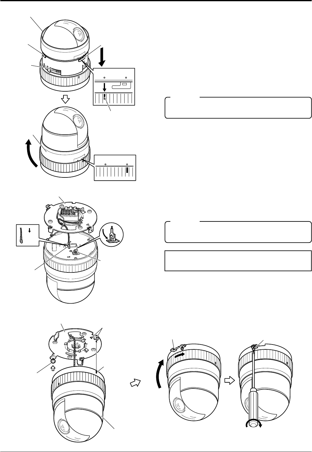
Attach the camera body cover.
Align "RELEASE on the camera body cover with the indi-
cation mark on the camera body, fit the cover onto the cam-
era body, then rotate the cover clockwise until “LOCK” is
indicated.
• Check that the three claws on the cover are locked onto
the camera body and that there is no clearance between
the cover and the camera body.
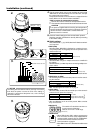
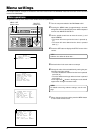
7.
Attaching the drop prevention wire.
As shown in the illustration, pull out the drop prevention
wire from the ceiling mount and engage it with the drop
prevention wire hook on the back of the camera.
Installation (continued)
Be sure to connect the drop prevention wire. Otherwise the
camera body may drop from the ceiling.
CAUTION
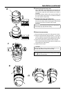
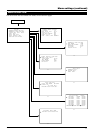
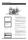
8.
Mount the camera body.
1) Ensure that the lock screw on the ceiling mount is loose.
2) Align the camera position alignment mark (^) on the ceil-
ing mount with the camera position alignment mark (
5
) on
the camera body and fit the camera body into the mount.
3) Rotate the camera body clockwise until it is checked.
Then, check that the camera body clamp is located on the
lock screw on the ceiling mount.
4) Tighten the lock screw.
Be sure to tighten the lock screw fully. Otherwise the cam-
era body may vibrate or drop from the ceiling.
CAUTION
For dismounting the camera from the ceiling, perform steps
1.
to
8.
in the reverse order.
LOCK
RELEASE
LOCK
RELEASE
Cover
Camera body cover
Setting
switches
Claw
Claw
6.
Indication
mark
LOCK
RELEASE
LOCK
RELEASE
7.
Ceiling mount on the ceiling
Drop prevention
wire
Pull
out.
Hook for attaching
the Drop prevention
wire
8.
Ceiling mount
on the ceiling
Camera position
alignment mark
Camera position
alignment mark
Lock screw
Camera body Rotate the camera
body clockwise.
Tighten the lock screw.
Lock screw
Camera clamp