


10
Follow these steps to connect the switchplate to
the antenna.
NOTE: System wiring diagrams are provided in
Appendix D on page 26.
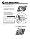
a. First dress the data and power cables from
the antenna. Strip back the insulation of each
wire approximately 1/4" (6 mm) and gently
twist each wire to ensure a good electrical
connection.
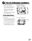
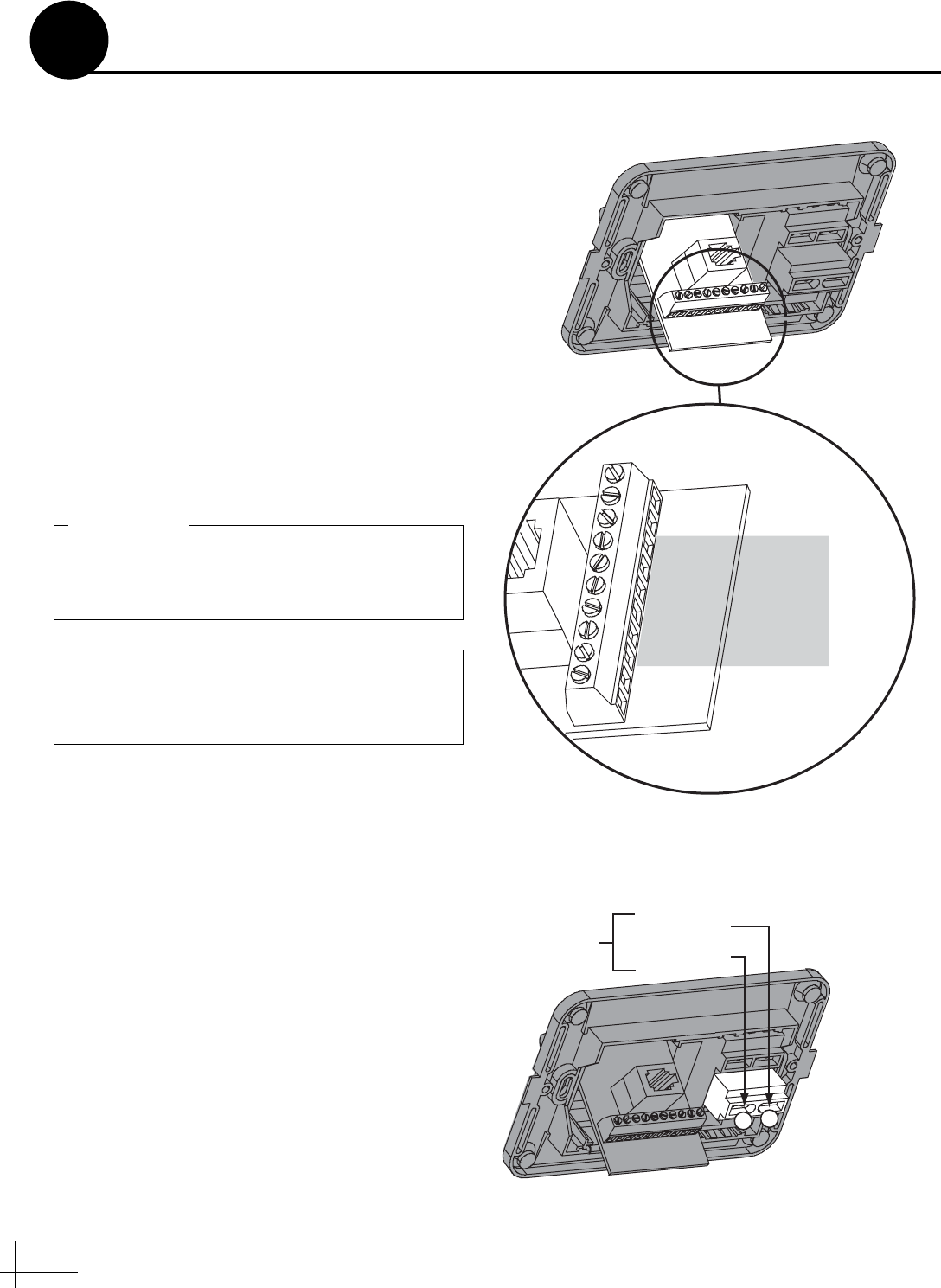
b. Connect the data cable from the antenna to
the terminal board on the back of the
switchplate (see Figure 19). Be sure to match
the wire colors with the terminal board label.
Tighten the terminal screws to secure all
wires in place.
c. Connect the power cable from the antenna to
the switchplate’s power output terminals (see
Figure 20).
BLU/WHT Not Used
WHT/BLU Not Used
BRN/WHT PC GND
WHT/BRN PC TXD
ORG/WHT PC RXD
WHT/ORG RF GND
GRY/WHT RF RXD
WHT/GRY RF TXD
GRN/WHT Not Used
WHT/GRN Not Used
Data Cable
to Antenna
Figure 19: Switchplate Wiring - Antenna Data Cable
The diagram refers to wires by body color/
stripe color. For example, “Blue/White”
means the blue wire with the white stripe.
IMPORTANT!
Do not connect the data cable’s drain wire
(shield) to anything. You can simply snip it
from the cable.
IMPORTANT!
+
–
+12 VDC (Red)
Ground (Black)
To Antenna
Figure 20: Switchplate Wiring - Antenna Power Cable
Wire the Switchplate
8