


5
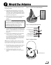
Before you begin, consider the following
switchplate installation guidelines:
• Select a switchplate mounting location in a
dry, well-ventilated area belowdecks away
from any heat sources or salt spray.
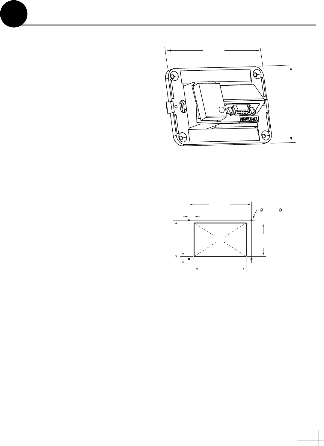
• Be sure to leave enough room at the
switchplate’s rear panel for connecting the
cables (see Figure 6 for switchplate
dimensions).
• Since the supplied data cable is 50 ft (15 m)
long, the switchplate must be located within
50 ft (15 m) of the antenna.
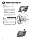
Prepare the Switchplate Mounting Site
Once you have identified a suitable switchplate
mounting site, follow these steps to prepare the
site for installation.
a. Using the switchplate mounting template
provided at the end of this manual, mark and
cut out a hole in the mounting surface to
accommodate the switchplate (see Figure 7).
b. Using the same template, mark the locations
for the four switchplate mounting holes.
c. Drill a 3/32" (2.25 mm) hole at the four
mounting hole locations. Later, you will
mount the switchplate using four #6 screws.
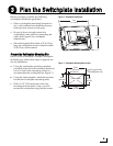
2.96"
(75.2 mm)
4.39"
(111.5 mm)
Figure 6: Switchplate Dimensions
3/32" ( 2.25 mm)
Mounting Hole (x4)
3.82"
(97 mm)
.32" (8 mm)
2.36"
(60 mm)
.16" (4 mm)
3.19"
(81 mm)
2.05"
(52 mm)
Panel Cutout
Figure 7: Switchplate Mounting Holes Layout
Plan the Switchplate Installation
3