Speedlight parts, their functions, and accessories
20
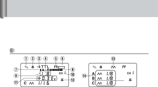
SU-800’s LCD panel and icons
Icons on the SU-800’s LCD panel show the status of the operations set.
These icons vary depending on the settings and the combination of camera and
flash units in use.
• The below illustrations are for reference only and may differ to the actual display.
Icons in close-up flash operation
1 Wireless Flash
A control signal is sent from the SU-800
to the remote flash units such as the
SB-R200.
2 Close-up Mode
Close-up function is set to “activated.”
3 Monitor Preflashes
Just before the flash fires, the Speedlight
fires a series of imperceptible preflashes
to collect necessary data for actual flash
firing.
4 TTL Mode
Measuring the flash illumination reflected
back from the subject, the camera
automatically controls the flash output
level to give the correct exposure.
5 Auto FP High-Speed Sync
Auto FP High-Speed Sync. is available
when the SU-800 is connected to
cameras compatible with Auto FP High-
Speed Sync. (p. 96).
6 Low Battery-power
Replace the battery.
7 Flash Output Level (Group A)
Visually indicates the group A’s flash
output level in the TTL mode.
8 Flash Output Level (Group B)
Visually indicates the group B’s flash
output level in the TTL mode.
9
Flash Output Level Ratio (Groups A : B)
Indicates the flash output level ratio
between groups A and B in the TTL
mode.
0 Channel
Represents the communication channel
number through which the SU-800 and
SB-R200 exchange data.
! Flash Output Level Compensation
(Groups A, B)
Represents flash output level
compensation for groups A and B in the
TTL mode.
@ CLS-compatible camera
The SU-800 is connected to cameras
compatible with CLS.
# Manual Flash
The flash always fires at a specified
output in combination with the aperture
and light output level (guide number).
$ Manual Flash Output Level
Represents flash output level for each
group in Manual flash mode.
Display in TTL mode Display in M (manual) mode


