


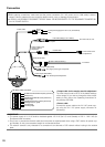
• 24 V AC power supply connector kit (accessory)
Recommended specification of cable (wire)
Wire size
(AWG),
stranded
wire
#24
(0.22 mm)
#22
(0.33 mm)
#20
(0.52 mm)
#18
(0.83 mm)
Length of
cable
20 m
{65.62 feet}
30 m
{98.43 feet}
45 m
{147.64 feet}
75 m
{246.06 feet}
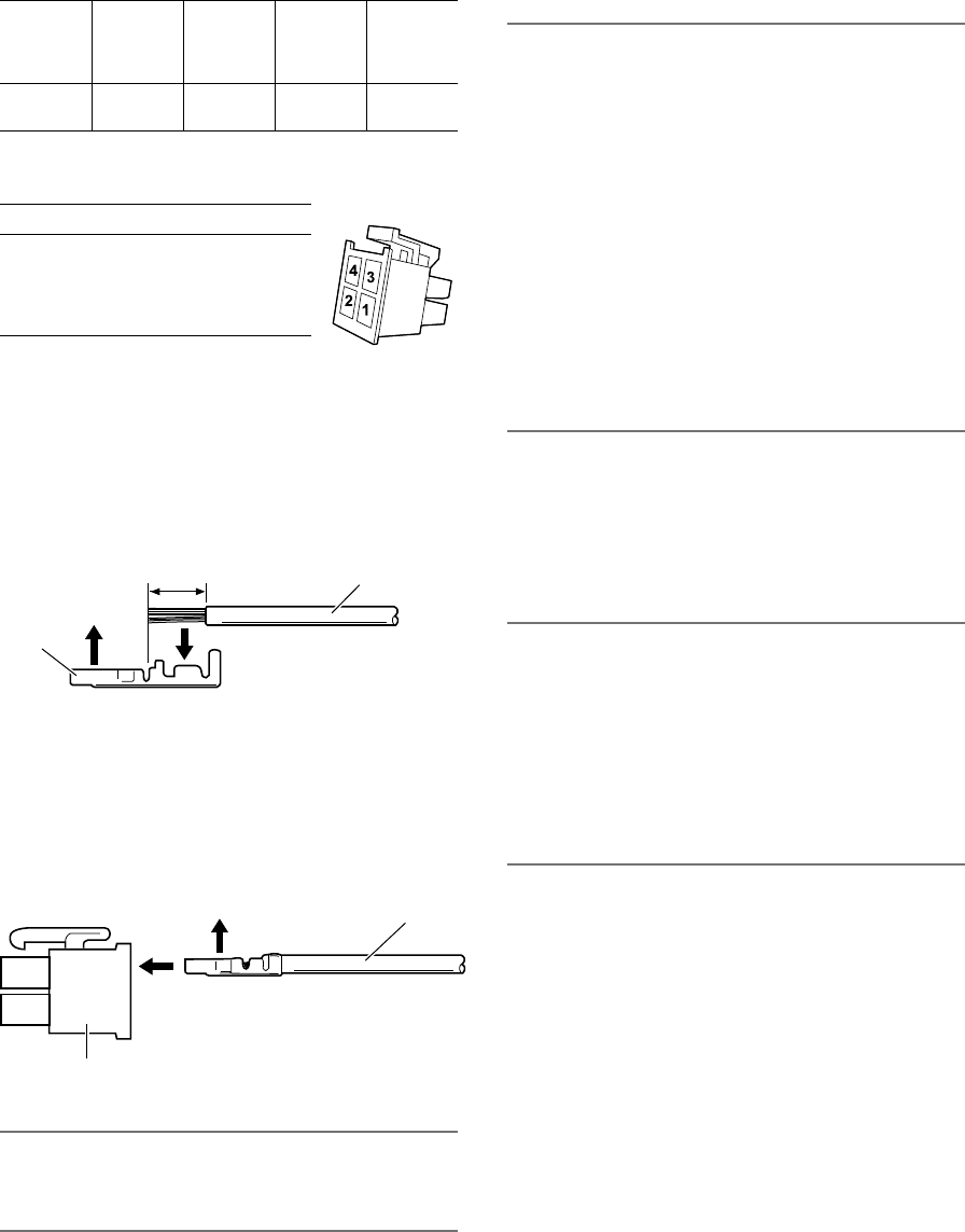
Power supply connector housing (accessory)
Pin No. Signal
1
2
3
4
24 V AC LIVE (Brown)
24 V AC NEUTRAL (Blue)
Ground (Green)
Not use
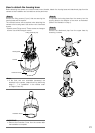
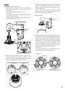
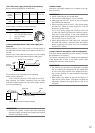
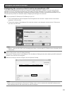
• How to assemble the 24 V AC power supply con-
nector kit
Remove approx. 3 mm {1/8 inches} of the outer jacket of
the cable and twist the cable core to prevent the short cir-
cuit first.
Insert the tip of the cable into the point A of the contact
(accessory), and hold the cable using the cable clamp.
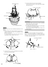
Procure either of the following tools for clamping.
Molex manual clamp tool:
57027-5000 (for UL1015), 57026-5000 (for UL1007)
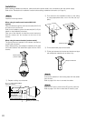
After clamping the contact (accessory) and the cable,
insert the contact properly into the power supply connec-
tor housing (accessory).
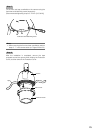
IMPORTANT:
• Conduct the electric conduit work after processing
the power supply connector and making sure that the
camera is operating normally.
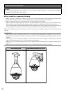
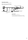
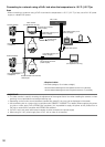
• Network cable
Connect a LAN cable (category 5e or better) to the net-
work connector.
IMPORTANT:
• Useall4pairs(8pins)oftheLANcable.
• Themaximumcablelengthis100m{328feet}.
• MakesurethatthePoE+deviceinuseiscompliant
with IEEE802.3at standard.
• Whenconnectingbothofthe24VACpowersupply
and the PoE+ device for power supply, 24 V AC will
be used for power supply.
If a 24 V AC power supply and a PoE (or PoE+) hub
or router are used at the same time, network connec-
tions may not be possible. In this case, disable the
PoE settings. Refer to the operating instructions of the
PoE (or PoE+) hub or router in use.
• WhendisconnectingtheLANcableonce,reconnect
the cable after around 2 seconds. When the cable is
quickly connected, the power may not be supplied
from the PoE+ device.
• Output cable for the monitor used for adjustment
Connect a coaxial cable (BNC) (only for checking if images
are displayed on the monitor).
This output is provided only for checking the adjustment
of the angular field of view on the video monitor when
installing the camera or when servicing.
IMPORTANT:
• Themonitoroutconnectorforadjustmentisprovided
only for checking the adjustment of the angular field
of view on the video monitor when installing the cam-
era or when servicing. It is not provided for recording/
monitoring use.
• Blackbandsmayappear atthetopand bottomor
right and left of the screen. (That does not affect the
adjustment because the angular field of view is not
changed.)
Contact
(accessory)
Insert
Upper
side
A
Approx. 3 mm {1/8 inches}
Cable
Contact (accessory)
Power supply connector housing (accessory)
Upper side
Cable
27