C1555M-G (12/07) 11
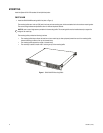
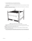
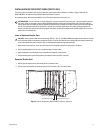
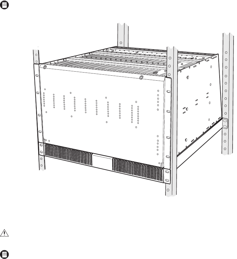
2. Install the CM9770-MXB matrix bay on top of the mounting baffle. Refer to Figure 2.
In a single-bay installation, always leave 1 RU of space above the matrix bay for airflow.
In a multiple-bay installation you do not need to leave additional RUs open between units. However, you must always leave 1 RU of space
above the upper bay.
Figure 2. Mounting the CM9770-MXB on Top of the Mounting Baffle
(Optional) Install additional CM9770-MXB mounting trays and matrix bays to the side of and below the first unit, as necessary.
3. Use the RJ-45 data cables supplied with each CM9770-MXB to connect the MXBs to the CC1. Refer to the Data Connections section and
the Port Assignments insert (supplied with the System 9770 documentation) for directions on which port to use for each MXB connection.
NOTE: Figure 2 illustrates the recommended mounting method. For an alternate, open-rack mounting method, refer to the Mounting the
CM9770-MXB in an Open Rack section in the Appendix.
WARNING: Always install equipment starting from the bottom of the rack frame or cabinet. Installing equipment from the top down will
make a rack or cabinet top heavy and could cause the equipment to tip over.
NOTE: Each CM9770-MXB has a unique label for identifying the bay location in the installation. This ID information is important in
ensuring correct video and data connections.


