6 Pelco Manual C418M (8/97)
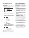
4.3 CAMERA/LENS INSTALLATION
AND ADJUSTMENTS
To install the camera/lens combination, perform
the following steps:
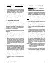
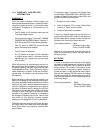
1. Disassemble the enclosure as specified in the
Maintenance Section, Section 7.0.
CAUTION
Pressure must be released prior
to opening the enclosure or per-
sonal injury may result.
2. Install the camera/lens on the camera sled
(Figure 10, item 11) by screwing the camera
to the sled.
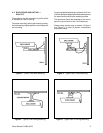
3. The enclosure power, lens functions and cam-
era power should be connected as follows
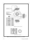
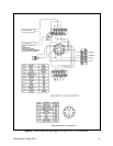
(also see Figures 7 and 8):
Pin # Function
A Video core
B Video shield
E Camera AC (high)
F Camera AC (low)
G Ground
H Enclosure AC (high)
K Iris
L Focus
M Zoom
N Lens Common
P Enclosure AC (low)
The EH8004, EH8006, EH8006-26 and
EH8008 also include lens preset capabilities.
Connections are as follows (refer to Figures 7
and 8):
Pin# Function
C Preset Positioning +5 V
D Preset Positioning Common
R Preset Positioning Focus
S Preset Positioning Zoom
Reinstall the camera sled into the body by follow-
ing the steps shown in the Maintenance, Section
7.3.
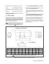
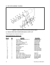
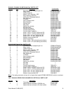
4.4 MATING CONNECTOR ASSEMBLY
To assemble the 16 or 11 pin mating connector for
the EH8000 Series Enclosures, perform the fol-
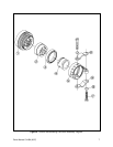
lowing steps and refer to Figure 6. Note that
enclosures supplied with an 11 pin connector will
be wired according to the diagram in the bottom
half of Figure 7 or 8.
1. Pass the coax and the enclosure control cable
through the cable clamp body (item 5), the cable
grommet (item 4), and the seal ring (item 3), in
that order. Push those components down the
cable approximately 10 inches (25 cm) to al-
low yourself room to work.
2. Strip the outer jacket from the coax and the
control cable back 2 inches. Strip the individual
conductors of the control cable back 1/4 inch
(0.63 cm).
3. Separate the coax shield from the core insu-
lation and twist into a single strand. Strip the
core insulation back 1 inch (3 cm).
4. Insert the individual conductors into the appro-
priate holes into the sealing grommet (item 2)
and force them through.
5. Solder the individual conductors to the appro-
priate pins in the connector body (item 1).
6. Push the sealing grommet ( item 2) into the
back of the connector body (item 1).
7. Slide the seal ring (item 3), the cable grommet
(item 4), and the cable clamp body (item 5) for-
ward to the connector body.
8. Thread the cable clamp body (item 5) onto the
connector body (item 1) and tighten.
9. Position the cable clamp halves (item 6), and at-
tach with the hardware supplied (items 7 and 8).
The cable clamp halves should apply pressure
to the cable grommet (item 4). Tighten all hard-
ware.


