


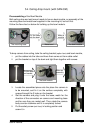
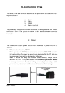

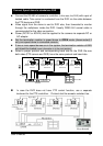
6.3 RS-485
The camera adapts RS-485 in half-duplex pattern, which
is a two-pin connectivity, as shown on the right picture.
Installer must pay attention to the polarity of these two
pins – yellow wire is the POSITIVE end, and orange is the
NEGATIVE. Communication between controller and
camera will break and control will not function if they are
reversely connected.
The RS-485 communication may run for 4,000 feet if the system network is properly
built. Two important factors should be handled with care during the system
build-up--- baud rate and termination impedance. More information about RS-485
are in sections “Protocol and Baud rate” and “Applications”.
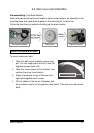
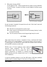
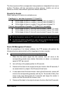
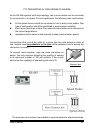
6.4 Alarm Input and Alarm Output
This camera is equipped with 3 alarm inputs and one alarm output for intrusion
management. Installers may connect the inputs to the various sensors and program
the camera to move and monitor specific spots for monitoring when evens take
place. Dwell time for monitoring is programmable, subject to the system. Refer to
the diagram on right for function assignments of the alarm I/O.
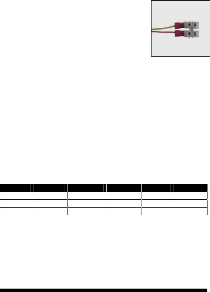
Alarm in Wire Color Alarm GND Wire Color Alarm out Wire Color
Alarm in 1 Black Alarm 1 Brown N.O. Gray
Alarm in 2 Red Alarm 2 Orange N.C. Purple
Alarm in 3 Yellow Alarm 3 Green Com. Blue
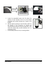
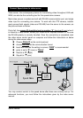
Alarm inputs
This speed dome has three alarm inputs, and each input is given by the software a
companion view preset. When trigger single is sent to alarm-in, the following
reactions will be taken by the speed dome:
The pan-tilt mechanism will move lens to the preset.
The alarm-out port will act.
Via RS-485, the console (control unit) will be notified
. .
User’s manual 28