v4.0
LDK 5481 + LDK 4700 User’s Guide | DigiLink system 1-6
1.5 Inte rcom
An intercom channel connects the base unit to the camera operator's headset. The operator's
intercom microphone signal is sent to the base unit. The headset can be connected to the 5
pin XLR headset connector at the back of the DigiLink adapter. For the connector and detailed
pin descriptions refer to chapter 2.7.7.
A conversation is started when the camera operator presses the VTR Start button at the front
of the camera or the VTR button on the lens. The function and behaviour of this button can be
defined in the INSTALL menu of the camera. Refer to the camera’s user’s guide.
The volume of the headset earmuffs can be adjusted by turning the audio volume knob at the
front (right side) of the camera.
Intercom configuration
The sidetone volume level (feedback signal from the microphone to the earmuffs) can be
adjusted withthe INSTALL/INTERCOM/SIDETONE function n the camera (available only when
a 4-wire connection is used).
Depending on the type of microphone the following items can be set in the INSTALL/
INTERCOM
menu in the camera:
• Microphone gain level (0 or +40 dB) with the CAM.MIC_GAIN function;
• Microphone power can be switched on or off with the CAM.MIC_POWER function.
Both 2-wire and 4-wire intercom connections can be used. On the base unit, set the setup
switch S1 in the Off-position when a 4-wire connection is used and set it in the On-position
when a 2-wire connection is used. Refer to chapter 3.5.2 for the description of the setup
switch.
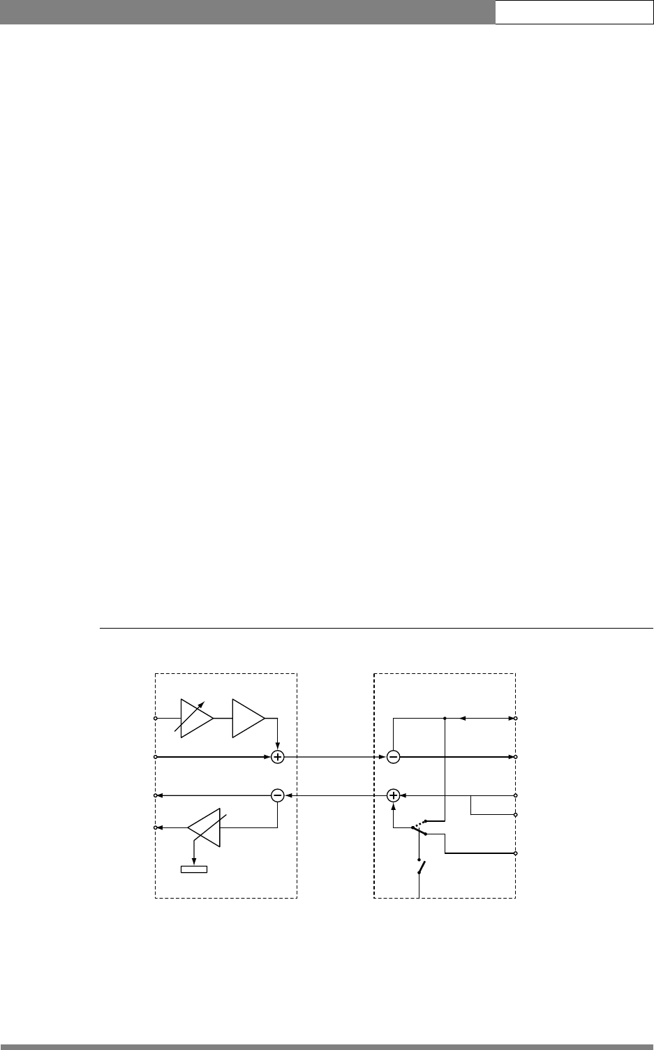
The following figure shows an overview of the routing of the intercom system. For the
connector and detailed pin descriptions refer to chapter 3.4.
Figure 1-8. Schematic overview of the intercom routing
DigiLink adapter DigiLink base unit
Cam SDI OUT
PROD out (4-wire)
PROD in/out (2-wire)
0 dBu
pin 1,9 return
PROD in (4-wire)
0 dBu
pin 5, 13 return
SDI
EXT
TP
Cam Video
0 / 40 dB
front volume
Cam SDI IN
S1 Off = 4-wire
S1 On = 2-wire
2 w.
4 w.
EXT/TP video
Out
0 dBu
Mic in
-24/-64 dBu


