


v4.0
LDK 5481 + LDK 4700 User’s Guide | Base unit 3-12
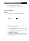
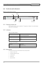
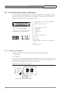
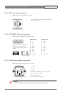
3.4 Connecting the studio signalling
Connect the studio signalling system to the rear of the base unit. The wiring of the panel
connector is shown below. Refer to the next chapter for the location of this connector.
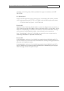
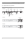
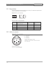
Figure 3-4. Signalling / Intercom / Auxiliary connector
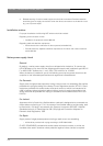
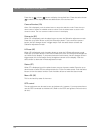
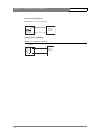
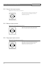
3.4.1 Call and On-air signals
There are two connection methods for the Call and On-air signalling functions:
1. Dry contact
2. Voltage level
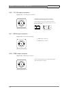
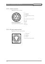
The connection method for the signalling functions is set by a jumper on the main board of the
base unit. Remove the upper lid of the base unit and locate jumper X317 at the bottom centre
of the board. The settings of the jumper are shown below:
Figure 3-5. Jumper settings for signalling
4
1
2
356
7
8
9
10 11 12
13
14
15
1 2 3 4 5 6
On
Side view of switches
Off
1. Intercom PROD Out (4-wire) or Intercom PROD In/Out
(2-wire)
2. Call send (dry contact to pin 10)
3. n.c.
4. On Air send (dry contact to pin 12)
5. Intercom PROD In
6. Private data In
7. Private data Out
8. Housing
9. Camera microphone Out return
10. Call return
11. n.c.
12. On Air return
13. Intercom PROD In return (4-wire) or not connected (2-
wire)
14. n.c.
15. Common ground
15-pin male D-connector; panel view
Panel part number: 2411 022 05292
A 4-wire (Off) or 2-wire (On) intercom system
is selected with rocker switch number 1.
+
C
A
12
D
19
B
26
5
+
L1500
K6000
MP7502
X312
R6005
C9507
C7516
IC7503
C1500
IC9500
C9503
R9531
X317
R9532
R9533
R9536
R9534
MP2004
R5021
MP2000
R2024
C2005
C2039
R2019
R2023
R2022
C7513
C
A
dry contact voltage level
D
B
C
A
D
B