


18
19
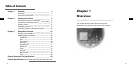
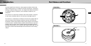
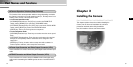
Installing the Camera
E E
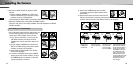
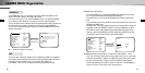
6. Remove the DOME COVER to adjust the LENS
direction.
1) Use the supplied L WRENCH to unfasten the 4
BOLTS for CASE fixing by turning them counter-
clockwise as shown in the illustration.
2) Disassemble the ASSY-DOME in the direction shown in the illustration.
7. Adjust the LENS direction and assemble the DOME COVER.
(Refer the steps 6 to 8 of the ceiling installation for LENS adjustment and DOME
COVER assembly.)
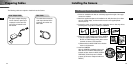
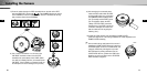
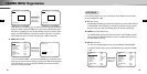
1. Pull out the power cable and video cable sticking out
from the PIPE assembly hole at the bottom of the
camera to the PIPE assembly hole on the side.
1) Use a “minus” screwdriver or a coin to turn the
CAP BOLT located on the side of the PIPE
assembly hole counter clockwise to remove the
CASE.
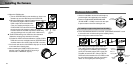
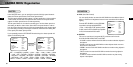
2) Use the supplied L WRENCH to unfasten the 4
BOLTS for CASE fixing by turning them counter-
clockwise as shown in the illustration.
3) Disassemble the ASSY-DOME in the direction
shown in the illustration.
4) Loosen the 2 SCREWS for fixing the CAMERA
body by turnin them counter clockwise, and turn
the CAMERA body in the direction of UNLOCK
(counter clockwise) to remove it.
SAMSUNG
SAMSUNG
For installing on a horizontal pipe
1)
2)
3)
4)
2)
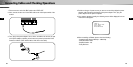
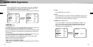
5) Remove the CAMERA body from the CASE.
(Completely separate the power cable from the
video cable.)
6) Disconnect the power and video cables from the
PCB and arrange them so that they can be passed through the PIPE
assembly hole on the side of the CASE as shown in the illustration.
Without passing throught the
center hole of the PCB, fas-
ten the cable to the cable fix-
ing clip from the outside of
the CAMERA, and then join
the CONNECTOR. (If the
cable is not fastened to the
cable fixing clip, any exces-
sive force applied to the cable
will directly affect the CON-
NECTOR and PCB and
cause damage.)
Disconnect the
CONNECTOR
from the PCB.
Remove the cable
from the cable fixing
clip.
Through the center
hole of the PCB,
remove the cable
from the CAMERA.
➠➠➠
➮
➮
➜
➜