


20
21
Installing the Camera
E E
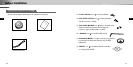
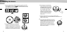
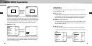
7) Route the cables through the PIPE assembly hole on the side of the PIPE,
align the INDEX KEY arrow mark ( ) of the CAMERA body to the groove
on the CAMERA, mount the CAMERA body and turn it clockwise all the way
tight, and then fasten the two SCREWS.
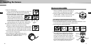
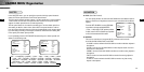
8) Use a “minus” screwdriver or a coin to turn the
CAP BOLT clockwise to fasten it to the PIPE
assembly hole at the bottom of the CASE. (Make
sure that an O RING (P22 T2.4) is inserted into the
CAP-BOLT. If the O RING is not inserted, it will not
be waterproof and cause damage to the product.)
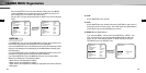
9) After arranging the connected power
cable and video cable inside the PIPE
and then pulling them out, put together
the CAMERA’s PIPE assembly screw
(3/4” Threaded) and the PIPE’s screw
(3/4” Threaded) to fasten the SET.
(*Wrap a TEFLON TAPE around the
threaded area of the PIPE to make the
connection watertight, and make sure
that the cables are not caught by the
fastening area.)
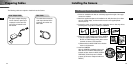
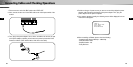
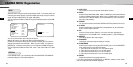
10) Adjust the LENS direction and assemble the DOME COVER.
(Refer the steps 6 to 8 of the ceiling installation for LENS adjustment and
DOME COVER assembly.)
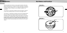
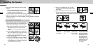
➣
How to switch the top and bottom of the screen if
installing the DOME COVER facing up Loosen the
STOPPER-RING, remove the COVER-LENS, and
rotate the LENS body 180 degrees so that the
BOTTOM mark is pointing downward. Put the
COVER-LENS back on, position the LENS in the
direction you want, and then turn the STOPPER-
RING clockwise to tighten it.
180º