


24
Basic Operations
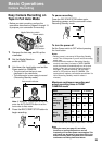
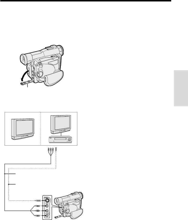
Watching the Playback on a
TV
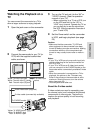
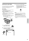
You can connect the camcorder to a TV to
allow a larger audience to enjoy playback.
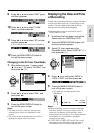
Jack cover
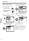
2 Connect the camcorder to your TV (or
VCR) with the supplied audio/video
cable, as shown.
POWER
TV/VCR SET UP
CHANNEL
REC
PLAY
STOP/
EJECT
PAUSE
/STILL
3 Turn on the TV and set it to the “AV” or
“VIDEO” channel. (See the operation
manual of your TV.)
• When connecting to a TV via a VCR, turn
on the VCR and set it to the “AV” or
“LINE” input channel. Operate the TV as
you normally do to see the signal from
the VCR. (See the operation manuals of
your TV and VCR.)
4 Set the Power switch on the camcorder
to VCR, and begin playback (see page
23).
Caution:
• Make sure that the camcorder, TV, VCR and
other equipment to be connected have been
turned off before you make connections. Making
connections with any of the components left
turned on may cause picture noise or malfunc-
tion.
Notes:
• If your TV or VCR has only one audio input jack,
use the white plug for the audio connection on
the TV or VCR.
• If your TV or VCR has an S-video input socket,
you can connect it to the S-VIDEO socket on the
camcorder with a commercially available S-video
cable.
• When the camcorder is connected to a TV for
playback, the picture on the TV screen may
flicker if the volume on the camcorder is set to
maximum. Should this occur, turn the volume
down (see page 23).
• Close the jack cover after use.
About the S-video socket
S-video sockets are used to separately pass
the chroma (color) and luminance (brightness)
components of video signals. They serve to
improve the picture quality in both recording
and playback.
S-video cable (commercially available)
To S-video input
socket
Yellow: To video input jack
White: To audio input (L) jack
Red: To audio input (R) jack
Audio/video cable (supplied)
To S-VIDEO socket
Yellow: To VIDEO jack
White: To AUDIO L jack
Red: To AUDIO R jack
1 Open the jack cover on the camcorder.